Solution dehumidifying fresh air unit using indoor exhaust evaporation cooling
A technology of evaporative cooling and fresh air unit, which is applied in energy recovery systems for ventilation and heating, applications, household heating, etc. It can solve the problems of limited fresh air cooling range and low humidity content, so as to improve indoor air quality and enhance cooling capacity, the effect of improving energy efficiency
- Summary
- Abstract
- Description
- Claims
- Application Information
AI Technical Summary
Problems solved by technology
Method used
Image
Examples
Embodiment 1
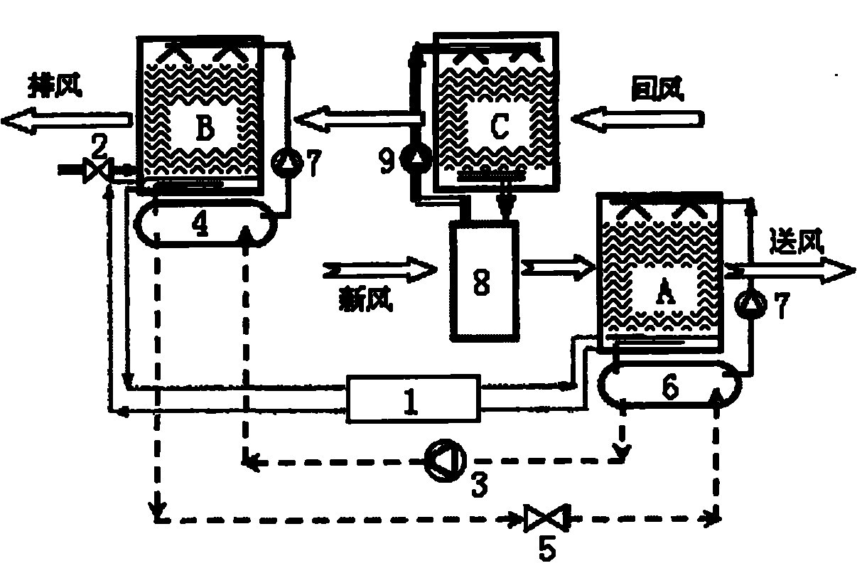
[0017] Such as figure 1 As shown, the fresh air unit in this embodiment includes a solution circulation system, a heat pump system and an evaporative cooling water system.
[0018] The solution circulation system includes an interstage solution circulation loop formed by connecting the dehumidification module A and the regeneration module B, and a plate heat exchanger 1 is arranged on the interstage solution circulation loop between the dehumidification module A and the regeneration module B. The regeneration module B is provided with a replenishment valve 2 for adjusting the concentration of the solution in the regeneration module B.
[0019] The heat pump system includes a heat pump circulation loop composed of a compressor 3, a condenser 4, a throttle valve 5 and an evaporator 6 connected in sequence, and the heat pump circulation loop is filled with refrigerant. The heat exchange end of the condenser 4 is connected to the regeneration module B through a solution circulati...
Embodiment 2
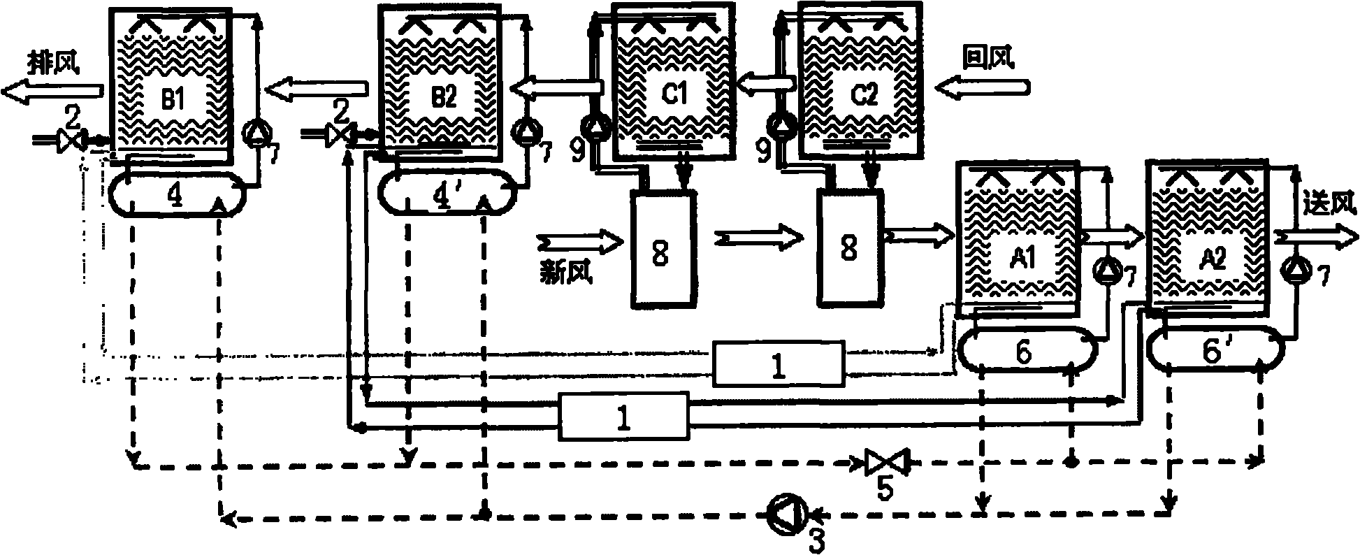
[0023] Such as figure 2 As shown, the difference between this embodiment and Embodiment 1 is that the fresh air unit of this embodiment includes two sets of dehumidification modules A1, A2, two sets of regeneration modules B1, B2 and two sets of evaporative cooling modules C1, C2, and the heat pump system includes Two heat pump circulation loops, compressor 3, condenser 4, throttle valve 5 and evaporator 6 are connected in sequence to form a heat pump circulation loop, which is used to cool the solution entering the dehumidification module A1 and heat the solution entering the regeneration module B1; the compressor 3. The condenser 4', the throttle valve 5 and the evaporator 6' are sequentially connected to form another heat pump cycle for cooling the solution entering the dehumidification module A2 and heating the solution entering the regeneration module B2. Since the dehumidification unit, regeneration unit and evaporative cooling unit in the fresh air unit of this embodim...
Embodiment 3
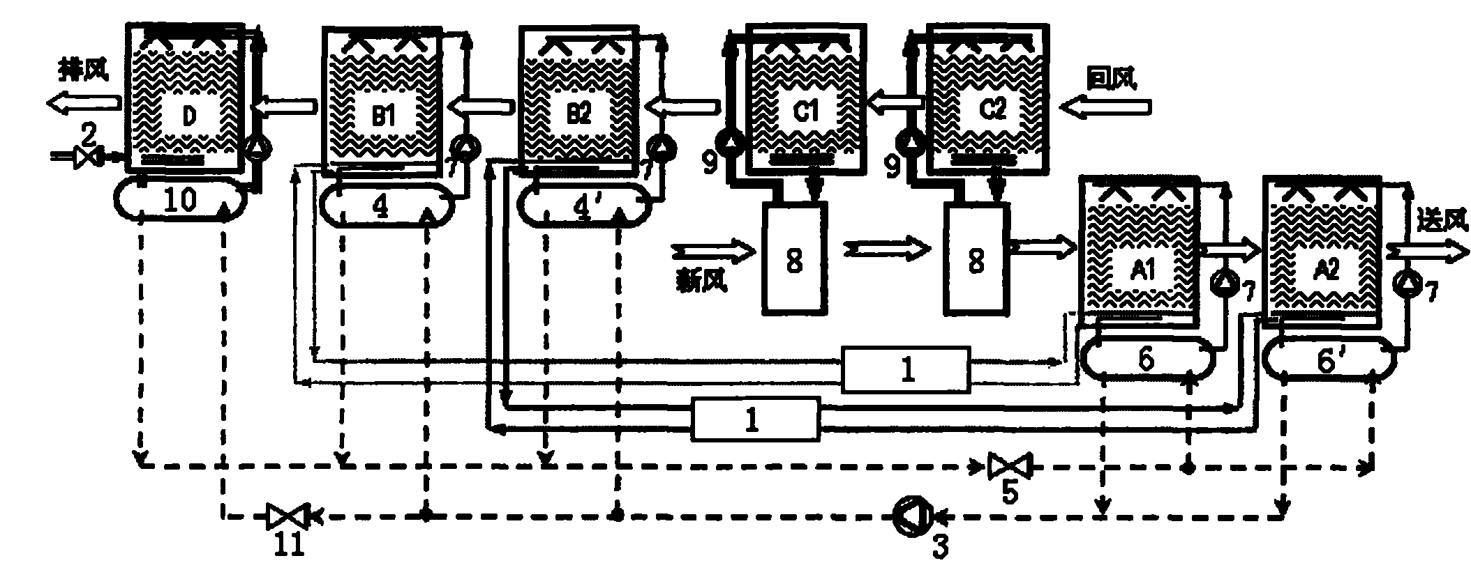
[0026] Such as image 3 As shown, the difference between this embodiment and Embodiment 2 is that an auxiliary evaporative cooling module D and an auxiliary condenser 10 are added to the fresh air unit of this embodiment, and the auxiliary evaporative cooling module D is arranged side by side outside the regenerative module B, and the auxiliary The evaporative cooling module D is connected to the heat exchange end of the auxiliary condenser 10 through a water circulation pump 9 to form a water heating circuit. The auxiliary condenser 10 is used to heat the water entering the auxiliary evaporative cooling module D, so as to discharge excess water from each condenser in the heat pump system. heat. The inlet of the heat exchange end of the auxiliary condenser 10 is connected in parallel with the outlet of the compressor 3 , the outlet of the heat exchange end of the auxiliary condenser 10 is connected in parallel with the inlet of the throttle valve 5 , and the inlet end of the a...
PUM
 Abstract
Description
Claims
Application Information
 - R&D
- Intellectual Property
- Life Sciences
- Materials
- Tech Scout
- Unparalleled Data Quality
- Higher Quality Content
- 60% Fewer Hallucinations
Browse by: Latest US Patents, China's latest patents, Technical Efficacy Thesaurus, Application Domain, Technology Topic, Popular Technical Reports.
© 2025 PatSnap. All rights reserved.Legal|Privacy policy|Modern Slavery Act Transparency Statement|Sitemap|About US| Contact US: help@patsnap.com


