
Quartz transmission polarization beam splitting grating for rectangular groove

A technology of polarization beam splitting and rectangular slots, applied in the direction of diffraction gratings, optics, optical elements, etc., can solve the problem of low diffraction efficiency of TE waves

Inactive Publication Date: 2010-09-29
SHANGHAI INST OF OPTICS & FINE MECHANICS CHINESE ACAD OF SCI
View PDF4 Cites 5 Cited by
  • Summary
  • Abstract
  • Description
  • Claims
  • Application Information

AI Technical Summary

Problems solved by technology

Although the design has higher diffraction efficiency for TM waves, the diffraction efficiency for TE waves is lower. Therefore, the efficiency can be further improved by improving the grating structure

Method used


Image

  • Quartz transmission polarization beam splitting grating for rectangular groove
  • Quartz transmission polarization beam splitting grating for rectangular groove
  • Quartz transmission polarization beam splitting grating for rectangular groove

Examples


Embodiment Construction

[0029] The present invention will be further described below in conjunction with the embodiments and accompanying drawings, but the protection scope of the present invention should not be limited thereby.

[0030] The basis of the present invention is as follows:

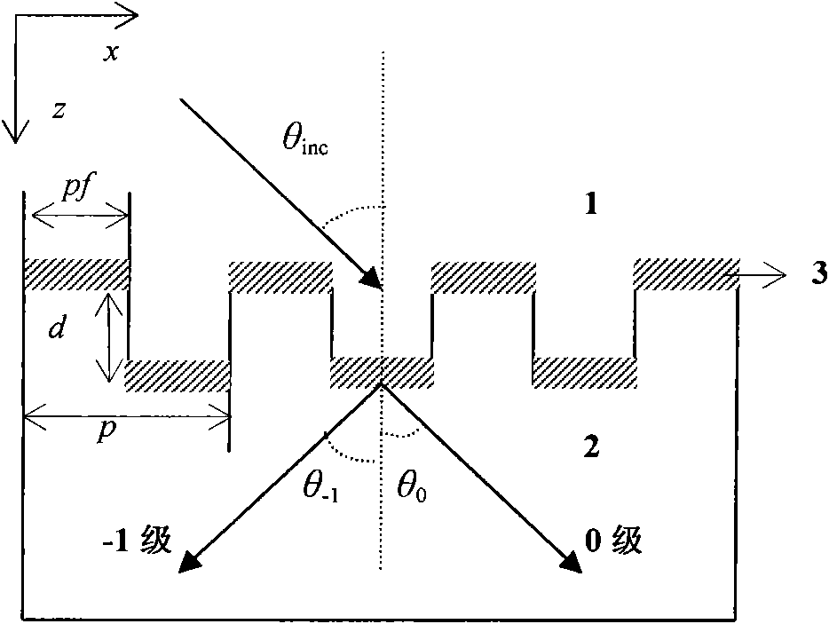
[0031] figure 1 It is a schematic diagram of the geometric structure of the rectangular groove quartz transmission polarization beam splitting grating of the present invention. Regions 1 and 2 are both homogeneous and are air (refractive index n 1 =1.0) and fused silica (refractive index n 2 =1.45), the shaded part is the porous silicon dioxide anti-reflection coating, and the refractive index can vary within the range of 1.22-1.29; p is the actual period of the grating, and d is the etching depth of the grating. The incident surface is perpendicular to the groove line of the grating, and a light wave is incident at the Littrow angle, that is, θ inc = sin -1 (λ 0 / 2n 1 p). Limit the period of the grating so ...


PUM


Abstract

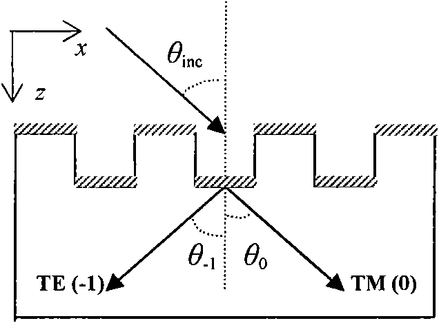
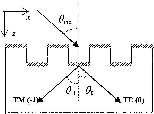
The invention relates to a quartz transmission polarization beam splitting grating for a rectangular groove. The grating comprises a fused quartz rectangular groove grating and a porous silica anti-reflection film on the surface thereof. The grating has two polarization ways: the first polarization way is to inflect TM wave to zero level and inflect TE wave to -1 level, wherein the variation range of normalization period rho, namely a rate of grating period to the incidence wave length, is 0.582 to 0.854, and the second polarization way is to inflect TM wave to -1 level and inflect TE wave to zero level, wherein the variation range of normalization period rho is 0.624 to 1.049. The diffraction efficiencies of the TE and TM waves of the quartz transmission polarization beam splitting grating for a rectangular groove of the invention can reach to 99% and the use wavelength range is wider.

Description

technical field [0001] The invention relates to a polarization beam splitting grating, in particular to a broadband rectangular groove quartz transmission polarization beam splitting grating whose diffraction efficiency of both TE wave and TM wave can reach more than 99%. Background technique [0002] Polarizing beam splitter is a key optical component, which can split the incident light into two beams of polarized light whose polarization directions are perpendicular to each other. It is widely used in polarization imaging systems, free-space optical switching networks and magneto-optical storage systems. In most applications, one usually requires a high extinction ratio, that is, high diffraction efficiency, wide operable wavelength range, small size, and low-cost polarization beam splitter. Traditional polarizing beam splitters are mostly designed and manufactured by utilizing the natural birefringence effect of crystals or the polarization characteristics of multilayer d...

Claims


Application Information

Patent Timeline
Patent Type & Authority Applications(China)
IPC IPC(8): G02B5/18G02B27/28
Inventor 毕群玉孙美智谢兴龙林尊琪
Owner SHANGHAI INST OF OPTICS & FINE MECHANICS CHINESE ACAD OF SCI
Learn More