Stereoscopic moulding device

A three-dimensional forming and three-dimensional technology, which is applied to spray devices, devices that apply liquid to surfaces, ceramic molding machines, etc., can solve problems such as inability to continue printing to produce high-quality 3D products, poor printing functionality, and blockage.

Inactive Publication Date: 2010-10-06
MICROJET TECH
View PDF0 Cites 45 Cited by
  • Summary
  • Abstract
  • Description
  • Claims
  • Application Information

AI Technical Summary

Problems solved by technology

[0007] Another object of the present invention is to provide a three-dimensional forming device to solve the problem that the traditional three-dimensional forming device cannot thoroughly clean the nozzle, and the nozzle is dry and blocked due to lack of moisture when the nozzle is sealed, resulting in damage to the nozzle and reducing the use of the nozzle lifespan, and cause poor functionality of subsequent printing, unable to c...

Method used


Image

  • Stereoscopic moulding device
  • Stereoscopic moulding device
  • Stereoscopic moulding device

Examples


Embodiment Construction

[0035] Some typical embodiments embodying the features and advantages of the present invention will be described in detail in the description in the following paragraphs. It should be understood that the present invention can have various changes in different aspects, all of which do not depart from the scope of the present invention, and the descriptions and diagrams therein are used for illustration in nature, not for limiting the present invention. invention.

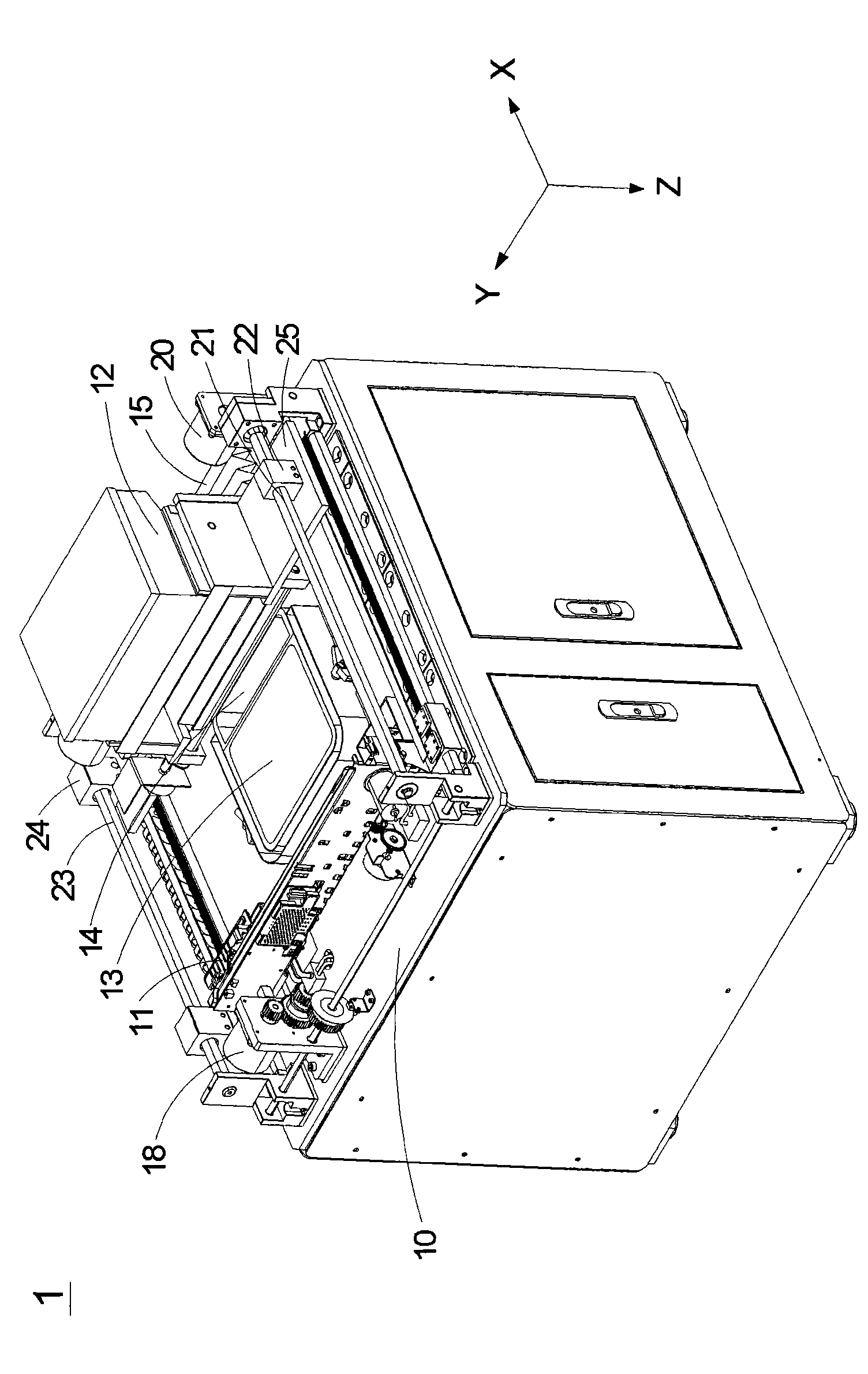
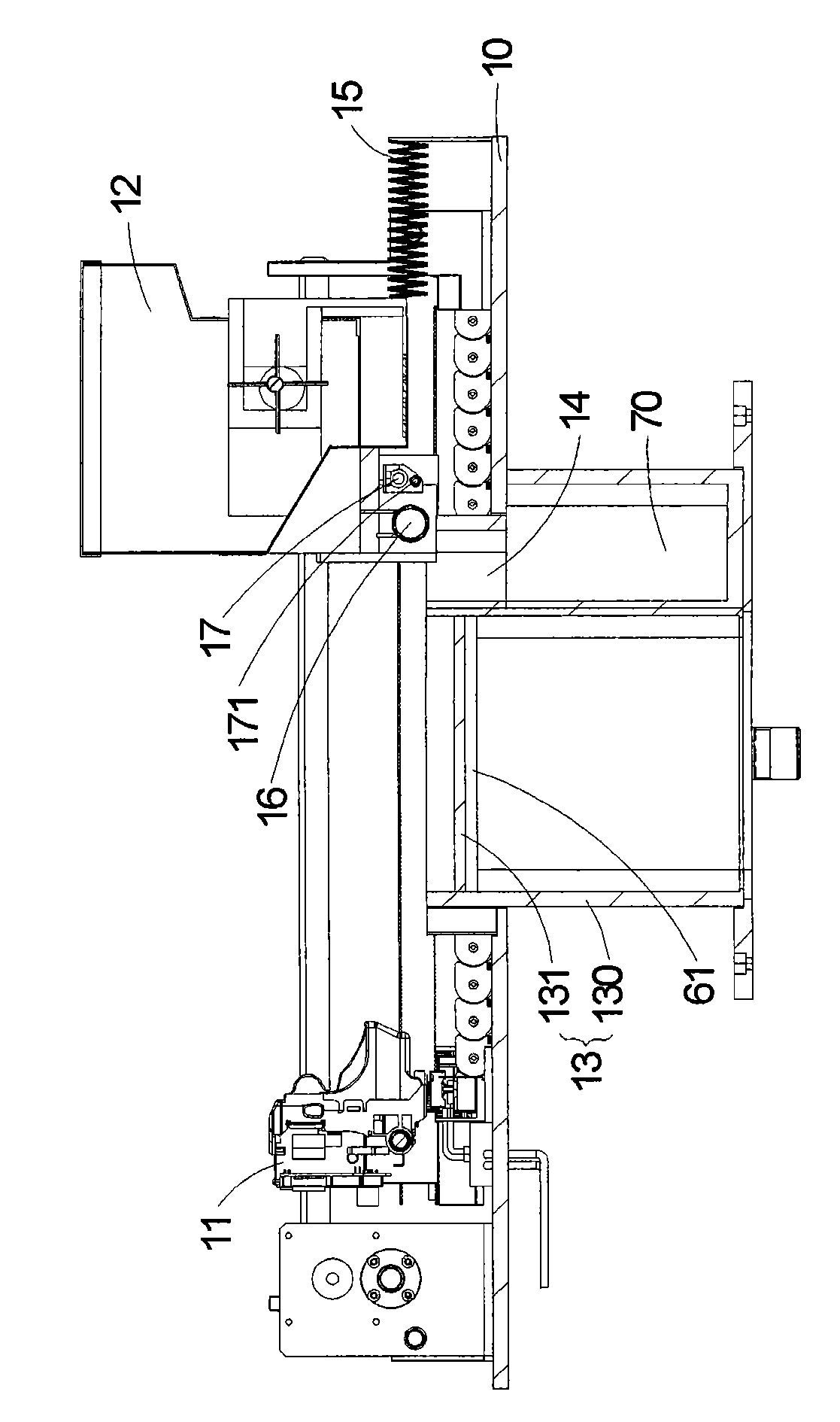
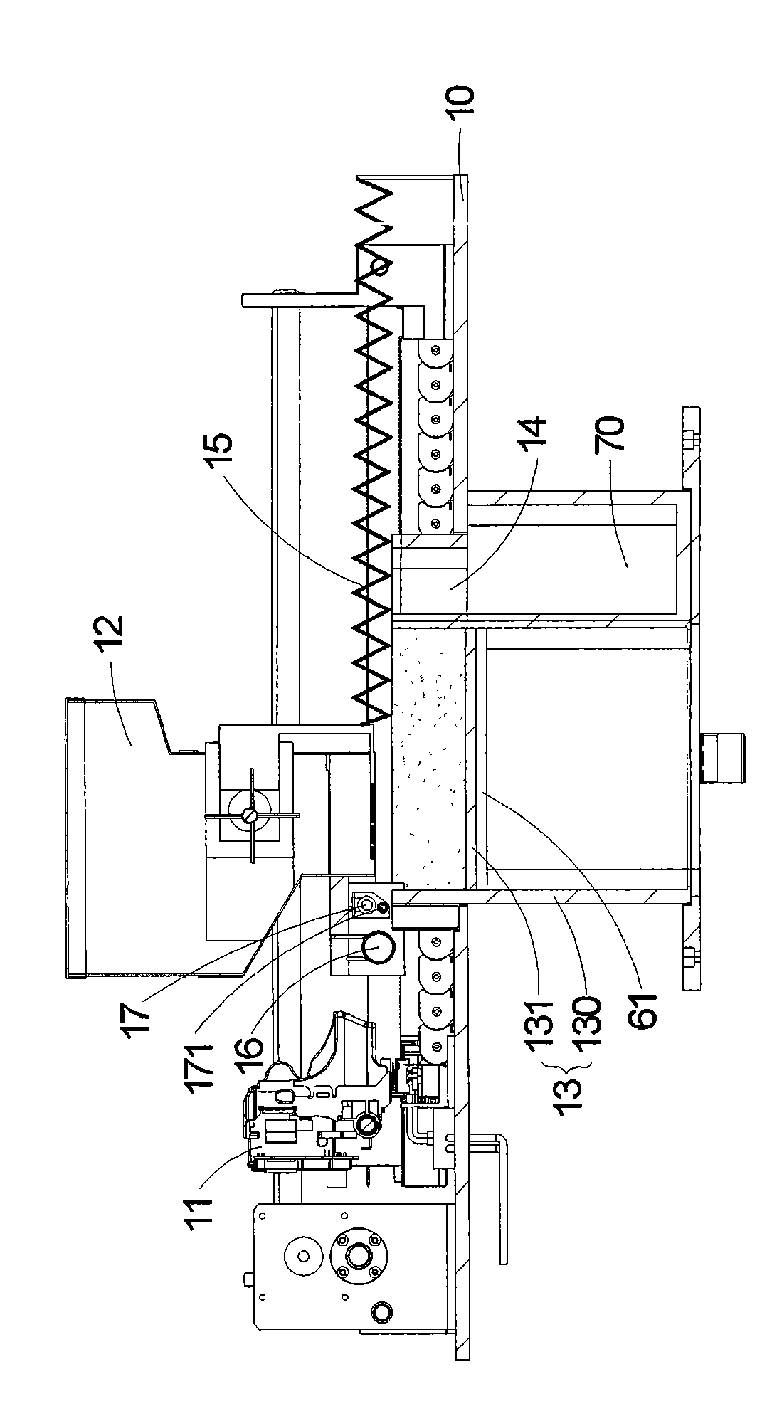
[0036] see Figure 1A , which is a schematic diagram of the three-dimensional structure of the table-top three-dimensional forming device in a preferred embodiment of the present invention. Such as Figure 1A As shown, the base platform 10 of the desktop three-dimensional forming device 1 of the present invention mainly includes a printing assembly 11, a powder supply tank 12 and a construction tank 13, wherein the tank body 130 of the construction tank 13 (such as Figure 1B (shown) extends downward from the base p...


PUM


Abstract

The invention relates to a stereoscopic moulding device, used for moulding a stereoscopic article. The stereoscopic moulding device at least comprises a dismountable construction tank, a movable powder supply tank, a printing assembly, a heating assembly, a lifting device, a spray nozzle cleaning device, a spray nozzle sealing device and a jet-printing moulding and powder spreading isolated operation device; wherein the movable powder supply tank can move above the dismountable construction tank to supply construction powder, so as to feed powder; the printing assembly is arranged below the dismountable construction tank; the spray nozzle sealing device comprises a bearing seat, at least one sealing part and a moisturizing device; the jet-printing moulding powder spreading isolated operation device comprises a telescopic dust boot which is connected with one side of the powder supply tank, so as to cover and be linked with the construction powder in the construction tank when the powder supply tank moves.

Description

technical field [0001] The invention relates to a three-dimensional forming device, in particular to a desktop three-dimensional forming device. Background technique [0002] Rapid prototyping technology (RP technology for short) is developed based on the concept of building a pyramid layer by layer. Its main technical feature is the rapidity of forming, and it can be molded without any tools, molds and fixtures. Automatically and quickly convert the design scheme of any complex shape into a 3D solid model, which greatly shortens the research and development cycle of new products and reduces the cost of research and development, and can ensure the time to market of new products and the first-time success rate of new product development. It provides a more complete and convenient product design communication tool between technical personnel and non-technical personnel such as enterprise decision makers and product users, thus significantly improving the competitiveness of pro...

Claims


Application Information

Patent Timeline
IPC IPC(8): B29C67/00B27N5/00B28B1/00B28B17/00B28B17/04B05C19/04B05C11/00B05C11/10B05C11/11B05C15/00B05C21/00B05B15/00B05B15/02
Inventor 奚国元董雅清
Owner MICROJET TECH
Why Eureka
Try Eureka