High-current metal ion source

A metal ion source and strong current technology, which is applied in the field of ion source and material surface treatment, can solve the problems of average current intensity and injection efficiency limitation, and achieve the effect of increasing divergence and convergence characteristics, improving uniformity, and increasing transmission extraction area

Active Publication Date: 2010-10-06
SOUTHWESTERN INST OF PHYSICS +1
View PDF0 Cites 15 Cited by
  • Summary
  • Abstract
  • Description
  • Claims
  • Application Information

AI Technical Summary

Problems solved by technology

Most of the current MEVVA ion sources can only generate pulsed metal ion flow, an

Method used


Image

  • High-current metal ion source
  • High-current metal ion source
  • High-current metal ion source

Examples


Embodiment 1

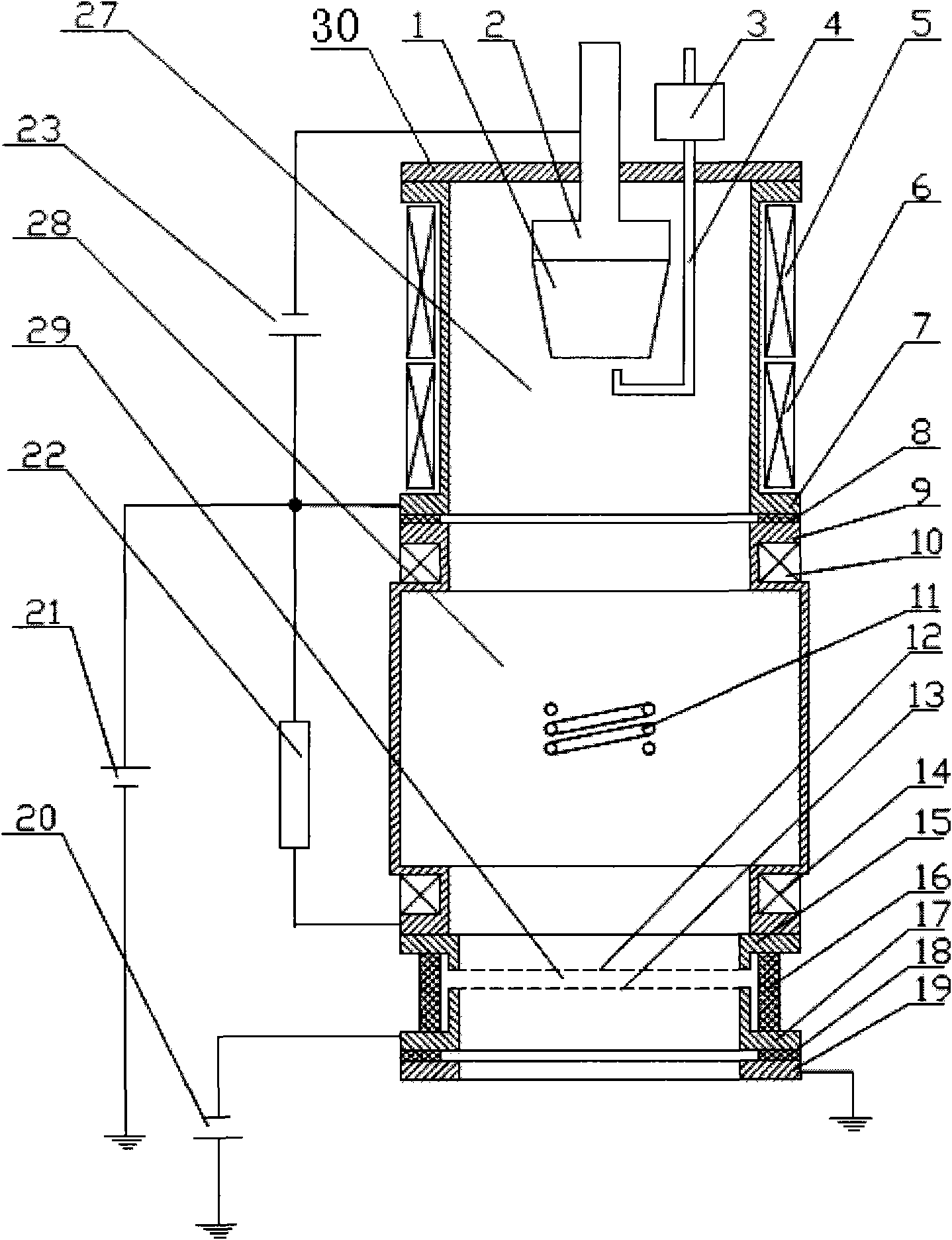
[0021] Such as figure 1 As shown, a high-current metal ion source includes a cathode 1, a water-cooled cathode seat 2, an anode cylinder 7, an arc stabilizing coil 5, a focusing coil 6, a trigger pin 4, a trigger wire package 3, a straight transport tube 9, Divergent coil 10, converging coil 14, insulating ring 8, lead-out grid 12, support flange 15, suppression grid 13, support flange 17, high-voltage insulating ring 16, deceleration power supply 20, acceleration power supply 21, water cooling screw Wire copper pipe 11, deceleration insulating ring 18, grounding flange 19, resistor 22 and arc discharge power supply 23. A groove is formed on the outer wall of the anode cylinder 7, and the arc stabilizing coil 5 and the focusing coil 6 are respectively wound in the groove, and the upper part of the anode cylinder 7 is connected with a flange cover 30 of ceramic material by screws. An inverted "T" shaped water-cooled cathode holder 2 passes through the central axis of the flang...

Embodiment 2

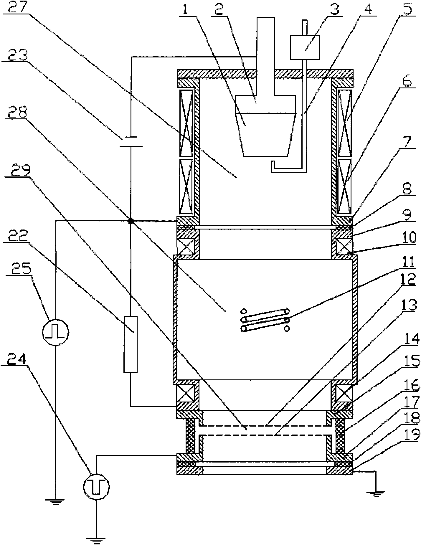
[0024] Such as figure 2 As shown, a high-current metal ion source includes a cathode 1, a water-cooled cathode seat 2, an anode cylinder 7, an arc stabilizing coil 5, a focusing coil 6, a trigger pin 4, a trigger wire package 3, a straight transport tube 9, Divergent coil 10, converging coil 14, insulating ring 8, lead-out grid 12, support flange 15, suppression grid 13, support flange 17, high-voltage insulating ring 16, deceleration power supply 20, acceleration power supply 21, water cooling screw Wire copper pipe 11, deceleration insulating ring 18, grounding flange 19, resistor 22 and arc discharge power supply 23. There is a groove on the outer wall of the anode cylinder 7, and the arc stabilization coil 5 and the focus coil 6 are respectively wound in the groove, and the upper part of the anode cylinder 7 is connected with a flange of ceramic material by screws. Cover 30. An inverted "T" shaped water-cooled cathode holder 2 passes through the central axis of the flan...

Embodiment 3

[0026] Such as image 3 As shown, a high-current metal ion source includes a cathode 1, a water-cooled cathode seat 2, an anode cylinder 7, an arc stabilizing coil 5, a focusing coil 6, a trigger pin 4, a trigger wire package 3, a straight transport tube 9, Divergent coil 10, converging coil 14, insulating ring 8, lead-out grid 12, support flange 15, suppression grid 13, support flange 17, high-voltage insulating ring 16, deceleration power supply 20, acceleration power supply 21, water cooling screw Wire copper pipe 11, deceleration insulating ring 18, grounding flange 19, resistor 22 and arc discharge power supply 23. A groove is formed on the outer wall of the anode cylinder 7, and the arc stabilizing coil 5 and the focusing coil 6 are respectively wound in the groove, and the upper part of the anode cylinder 7 is connected with a flange cover 30 of ceramic material by screws. An inverted "T" shaped water-cooled cathode holder 2 passes through the central axis of the flang...


PUM


Abstract

The invention discloses a large-area, high-energy and high-current metal ion source which can work under two modes of direct current and pulse. The invention is characterized in that an magnetic field is adopted to control a cathode arc to discharge electricity to produce a direct current metal plasma; the direct current metal plasma is transported to an ion leading-out area by a magnetic-mirror field and then is accelerated by a grid to obtain a high-energy ion beam; an reversal magnetic island formed by a solenoid is additionally arranged at the middle of a plasma transporting area, can improve the uniformity of the output plasmas, prevents large particles from entering the ion leading-out area and improves the uniformity and the stability of the ion beam; the ion beam leading out and accelerating modes adopt a direct current or a pulse mode so as to obtain pure ion beams or the plasmas/the ion beams; and an air feed pipe is utilized to fill working gas into a plasma generating area to lead the working gas to participate in plasma discharging to obtain metal-gas mixed ion beams. The device of the invention can be used for injecting and depositing high-quality reacting film on a workpiece, filling ions, carrying out ion plating and the like.

Description

Technical field: [0001] The invention belongs to the field of ion source and material surface treatment, in particular to a high-current metal ion source. Background technique: [0002] With the development of high-energy gas ion source and metal ion source, especially the invention of MEVVA ion source, the application of ion implantation technology is becoming more and more extensive. Because the MEVVA ion source can generate high-energy ion flow of most metals and semiconductor elements, the application range of ion implantation technology is gradually expanded. Ion implantation technology is widely used in the surface modification of metal materials to improve the surface properties of metal materials, such as friction, wear and corrosion resistance. At the same time, the application of ion implantation technology in the surface treatment of semiconductor and non-metallic materials is becoming more and more extensive, such as semiconductor doping and ceramic surface meta...

Claims


Application Information

Patent Timeline
IPC IPC(8): C23C14/48C23C14/34C23C14/38C23C14/46
Inventor 唐德礼童洪辉蒲世豪谢峰赵杰耿少飞张华芳武洪臣刘亮
Owner SOUTHWESTERN INST OF PHYSICS
Why Eureka
Try Eureka