Heat regenerative liquid fuel micro-burner

A technology of liquid fuel and micro-combustor, which is applied in the field of micro-energy systems, can solve the problem of liquid fuel ignition, exhaust heat loss is difficult to be solved well, and achieve the effects of not being easy to extinguish, realizing waste heat utilization, and stable combustion

Inactive Publication Date: 2011-12-28
SOUTH CHINA UNIV OF TECH
View PDF0 Cites 2 Cited by
  • Summary
  • Abstract
  • Description
  • Claims
  • Application Information

AI Technical Summary

Problems solved by technology

But even so, the ignition of liquid fuel in the micro-scale space and the heat loss of exhaust gas are still difficult to solve well

Method used


Image

  • Heat regenerative liquid fuel micro-burner
  • Heat regenerative liquid fuel micro-burner
  • Heat regenerative liquid fuel micro-burner

Examples


Embodiment Construction

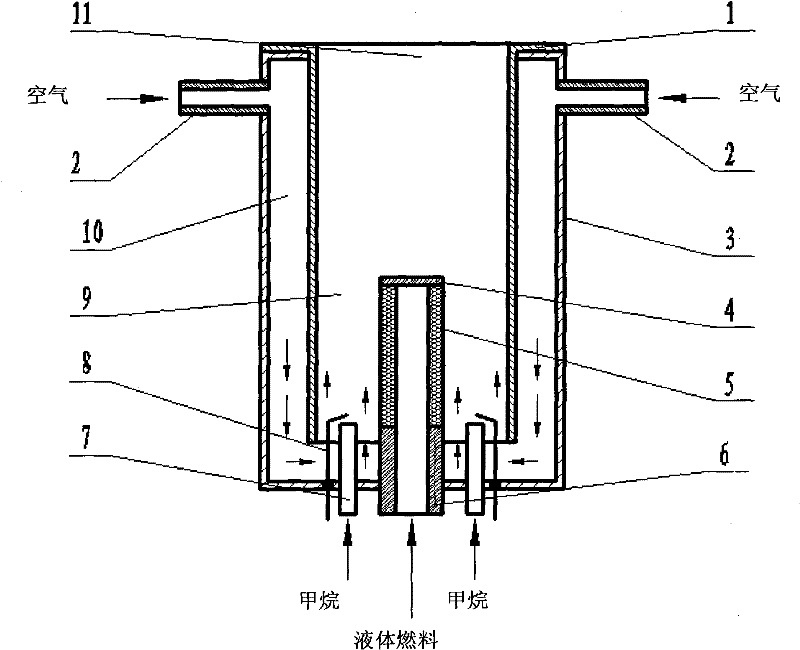
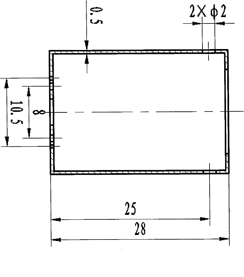
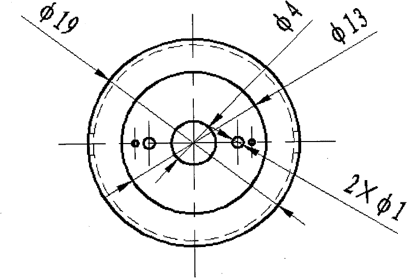
[0031] Such as figure 1 As shown, a recuperative liquid fuel micro burner includes an exhaust outlet 11, an outer cylinder 3, an inner cylinder 1, an air nozzle 2, a combustion chamber 9, an igniter 8, a methane gas nozzle 7 and a liquid fuel The nozzle 6 also includes an annular space 10 between the inner cylinder 1 and the outer cylinder 3, and a porous medium atomizing pipe 5 welded and fixed on the liquid fuel nozzle 6; the bottom of the annular space 10 communicates with the combustion chamber, and the air can Pass through the bottom of the inner cylinder 1 and enter the combustion chamber 9, and the top end is welded and sealed with the sealing cover plate 4. The air nozzles 2 are symmetrically arranged on both sides of the burner outer cylinder 3 , and the methane gas nozzles 7 are symmetrically arranged on both sides of the liquid fuel nozzle 6 . The cross sections of the inner cylinder 1, the air nozzle 2, the burner outer cylinder 3, the porous medium atomizing pipe...


PUM


Abstract

The invention discloses a heat regenerative liquid fuel micro-burner which comprises an exhaust gas vent (11), an outer barrel (3), an inner barrel (1), an air spray pipe (2), a burning chamber (9), an igniter (8), an methane gas spray pipe (7), a liquid fuel spray pipe (6), a circular space (10) between the inner barrel (1) and the outer barrel (3), and aporous media atomization tube (5) fixed on the liquid fuel spray pipe (6); the bottom of the circular space (10) is communicated with the burning chamber (9), the porous media atomization tube (5) is communicated with the liquid fuel spray pipe (6), and a top end is sealed by a seal cover plate (4). The heat regenerative liquid fuel micro-burner realizes the partial recovery and utilization of exhaust gas heat, reduces the cooling lossesand improves the burning efficiency, and simultaneously the air is pre-heated and stable burning is facilitated.

Description

technical field [0001] The invention relates to the field of micro energy systems, in particular to a regenerative liquid fuel micro burner. technical background [0002] Micro-scale combustion is proposed with the development of MEMS (micro-electro-mechanical systems) technology. This kind of combustion has the characteristics of high energy density and combustion scale below 1 cubic centimeter. Therefore, using a micro-energy system based on micro-scale combustion to provide electrical energy for portable electronic devices has greater advantages than traditional chemical battery functions, such as micro-aircraft, micro-satellite propulsion systems, and scientific and technological combat humanoid robots. energy supply system. [0003] However, the micro-scale burner is not just a simple scale reduction of the traditional burner, it also creates many new technical problems, such as the reduction of the size of the burner at the micro-scale compared to the conventional bur...

Claims


Application Information

Patent Timeline
Patent Type & Authority Patents(China)
IPC IPC(8): F23D11/00F23D11/44F23Q7/06
CPCY02E20/34
Inventor 甘云华袁坚杨泽亮
Owner SOUTH CHINA UNIV OF TECH
Why Eureka
Try Eureka