
Adjustable optical switch

A technology of optical switches and transparent substrates, applied in optics, optical components, instruments, etc., can solve the problems of complex preparation process and easy breakdown of the insulating layer, and achieve the effect of simple structure and low working voltage

Inactive Publication Date: 2010-10-06
高婧
View PDF6 Cites 9 Cited by
  • Summary
  • Abstract
  • Description
  • Claims
  • Application Information

AI Technical Summary

Problems solved by technology

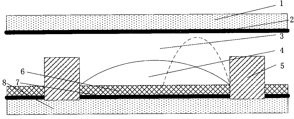
[0009] In order to overcome the complex preparation process of the insulating layer in the existing electrowetting optical switch and the problems of easy breakdown, the present invention provides an adjustable optical switch based on dielectrophoretic technology, which does not need an insulating layer to cover the conductive electrode, has a simple structure, and works low voltage

Method used


Image

  • Adjustable optical switch
  • Adjustable optical switch
  • Adjustable optical switch

Examples


Embodiment Construction

[0032] The present invention will be further described below in conjunction with accompanying drawing:

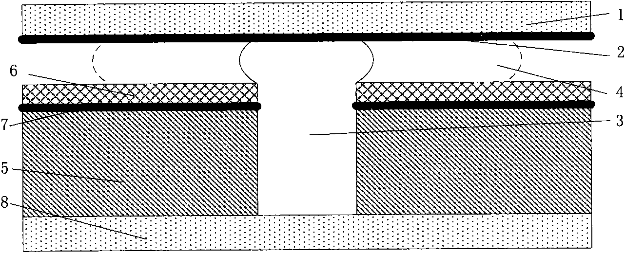
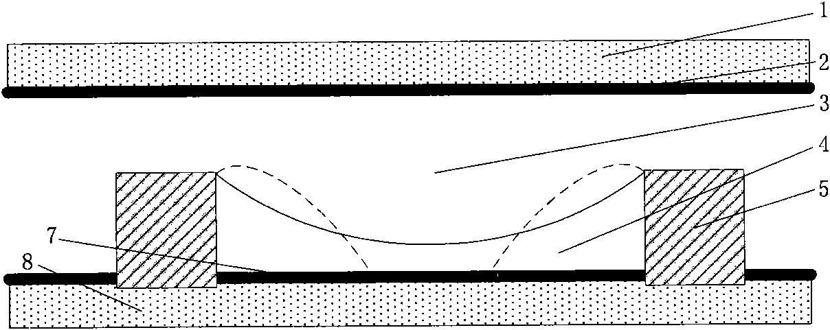
[0033] figure 2 Shown is a schematic diagram of the first preferred structure of the dielectrophoretic optical switch proposed by the present invention. figure 2 Shown is a cross-sectional view. The first substrate 1 is a transparent substrate, and its material may be glass, transparent resin, polyimide, or polyethylene terephthalate (PET). On the first substrate 1 is the first electrode 2, the first electrode 2 can be a two-dimensional planar electrode, or various two-dimensional patterns designed to control the spatial electric field distribution, the first electrode 2 can be metal such as aluminum, copper, etc. The electrode is preferably a transparent conductive electrode such as indium tin oxide ITO in the present invention. Below the first electrode 2 are an immiscible first liquid 3 and a second liquid 4, both of which are non-conductive, and the first liquid 3 ...


PUM


Abstract

The invention discloses an adjustable optical switch, which comprises a first transparent substrate (1), a second transparent substrate (8), first liquid (3) and second liquid (4). The adjustable optical switch is characterized in that: the second transparent substrate (8) is provided with a second electrode (7); the first liquid (3) and the second liquid (4), which are non-conducting, are accommodated between the first transparent substrate (1) and the second transparent substrate (8); and the second transparent substrate (8) is provided with a partition wall (5). Compared with the optical switch adopting the traditional electrowetting technique, the adjustable optical switch of the invention has the advantages of no need of insulating layer, simple structure and low driving voltage.

Description

technical field [0001] The invention relates to an adjustable optical switch, in particular to an optical switch modulated by electric field force. Background technique [0002] Optical switch arrays are widely used in display technologies. For example, liquid crystal displays control the output light intensity of each display pixel by modulating the direction of liquid crystal molecules. However, the traditional liquid crystal display has the problem of a decrease in contrast ratio under strong light irradiation. Especially under outdoor sunlight, the readability of the screens of mobile phones, notebook computers, e-books and other products using LCD screens decreases due to the decrease in display contrast. [0003] The optical switch array based on electrowetting technology overcomes the contrast drop problem of liquid crystal display. The current mainstream electrowetting display mainly has two working modes. The first display method is as Figure 1a shown [1] , the...

Claims


Application Information

Patent Timeline
Patent Type & Authority Applications(China)
IPC IPC(8): G02B26/02
Inventor 高婧
Owner 高婧
Learn More