Anti-clogging coal-fired industrial furnace

A technology for slag-burning coal and kilns, applied in the field of industrial kilns, can solve the problems of low efficiency, serious slagging and high NOx emission, and achieve the effects of solving slag formation in the furnace, improving the efficiency of the kiln and reducing the temperature of the furnace chamber

Inactive Publication Date: 2010-10-13
HARBIN INST OF TECH
View PDF7 Cites 4 Cited by
  • Summary
  • Abstract
  • Description
  • Claims
  • Application Information

AI Technical Summary

Problems solved by technology

[0003] The purpose of the present invention is to solve the problems of low efficiency, serious slagging and high NOx emission in current coal-fired industrial kilns using adiabatic furnaces, and proposes an anti-slagging coal-fired industrial kiln

Method used


Image

  • Anti-clogging coal-fired industrial furnace
  • Anti-clogging coal-fired industrial furnace
  • Anti-clogging coal-fired industrial furnace

Examples


specific Embodiment approach 1

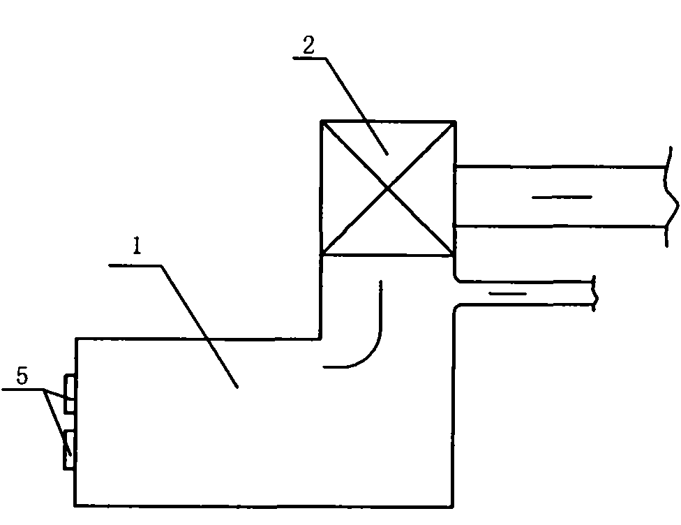
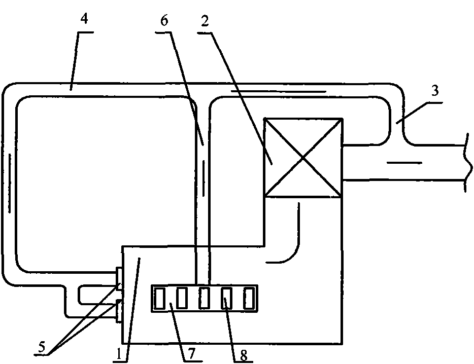
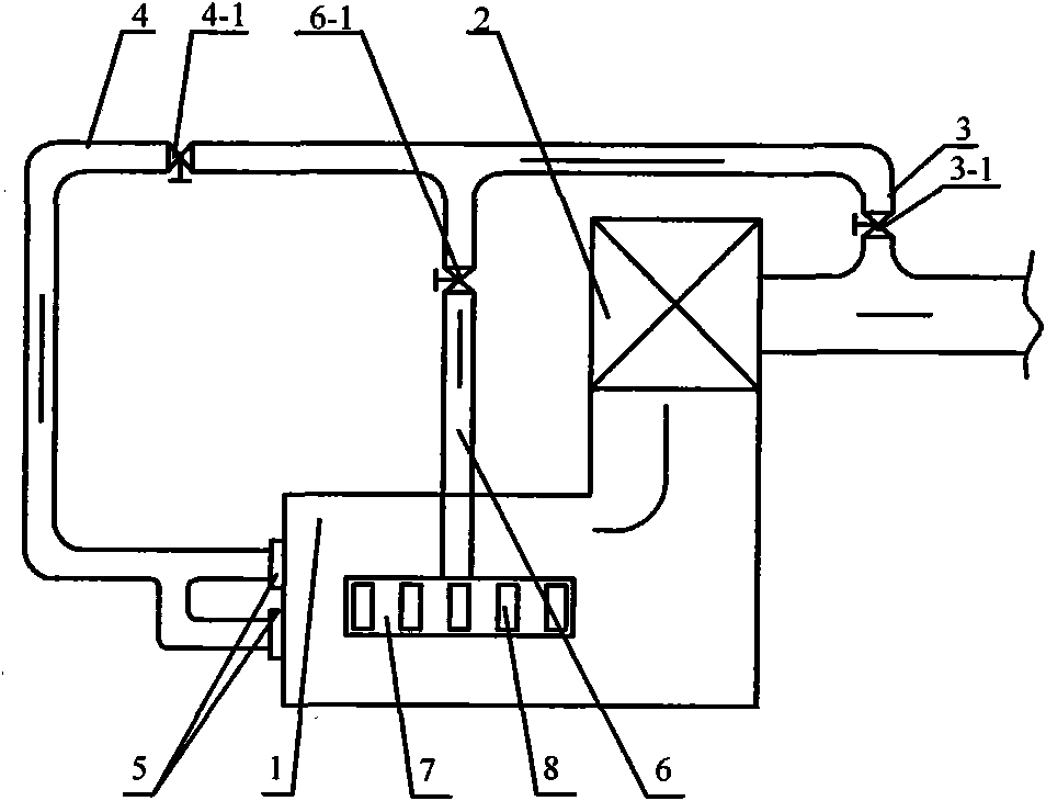
[0008] Specific embodiment one: combination figure 2 with image 3 To illustrate this embodiment, the kiln of this embodiment includes an adiabatic furnace 1 and a flue gas utilization device 2. The kiln also includes a flue gas recirculation main pipe 3, a first flue gas recirculation sub-pipe 4, and a set of smoke The cyclone pulverized coal burner 5 for gas recirculation, the second flue gas recirculation sub-pipe 6, and a set of flue gas recirculation nozzles 8, the outlet of the adiabatic furnace 1 is connected to the flue gas utilization equipment 2, and the flue gas utilization equipment The outlet of 2 is connected to the inlet of the flue gas recirculation main pipe 3, and the outlet of the flue gas recirculation main pipe 3 is respectively connected to the inlet of the first flue gas recirculation sub-pipe 4 and the inlet of the second flue gas recirculation sub-pipe 6 , The outlet of the first flue gas recirculation sub-pipe 4 is in communication with the correspondi...

specific Embodiment approach 2

[0009] Specific implementation manner two: combination image 3 To explain this embodiment, the kiln of this embodiment also includes a flue gas recirculation main baffle 3-1. The flue gas recirculation main pipe 3 is equipped with a flue gas recirculation main baffle 3-1. This structure can be controlled The amount of recirculated flue gas thus controls the inlet flue gas temperature and furnace temperature of the flue gas utilization device 2. Other components and connection relationships are the same as those in the first embodiment.

specific Embodiment approach 3

[0010] Specific implementation mode three: combination image 3 To explain this embodiment, the kiln of this embodiment further includes a first flue gas recirculation baffle 4-1, and the first flue gas recirculation sub-pipe 4 is equipped with a first flue gas recirculation baffle 4-1, This structure can control the amount of recirculated flue gas leading to a set of swirling pulverized coal burners 5 with flue gas recirculation. Other components and connection relationships are the same as those in the first embodiment.


PUM


Abstract

The invention relates to an anti-clogging coal-fired industrial furnace which relates to an industrial furnace. The invention aims to solve the problems of low efficiency, serious slag bonding and high NOx discharge amount of the coal-fired industrial furnace adopting a heat-insulating hearth at present. The invention adopts twp schemes that: scheme 1: the heat-insulating hearth is connected with smoke gas utilization equipment, the smoke gas utilization equipment is communicated with a smoke gas recirculation main pipeline, the smoke gas recirculation main pipeline is respectively communicated with a first smoke gas recirculation branch pipeline and a second smoke gas recirculation branch pipeline, the first smoke gas recirculation branch pipeline is communicated with a corresponding swirl pulverized coal burner with smoke gas recirculation, a group of swirl pulverized coal burners with smoke gas recirculation are arranged on the front wall of the heat-insulating hearth, and an a group of smoke gas recirculation spouts are communicated with the second smoke gas recirculation branch pipeline; and the different point of the scheme 2 is as follows: the outlet of the smoke gas utilization equipment is communicated with the inlets of the first smoke gas recirculation branch pipeline and the second smoke gas recirculation branch pipeline. The invention is applied to the industrial field of material drying by utilizing hot smoke gas.

Description

Technical field [0001] The invention relates to an industrial kiln. Background technique [0002] Industrial kilns mainly refer to equipment built with refractory materials to burn materials or burn products. The development of industrial kilns in our country has been rapid and has been widely used in various fields of industrial production. According to different fuel types, industrial kilns can be divided into coal-fired industrial kilns, oil-fired industrial kilns, gas-fired industrial kilns and bio-fuel industrial kilns. Generally, the fuel for large-scale kilns is mostly heavy oil, light diesel or coal gas and natural gas. As my country's primary energy is coal, the proportion of industrial furnaces that use coal as fuel will continue to increase. In the industrial field, industrial kilns that use hot flue gas are widely used, such as using flue gas to dry cement retarders. Such industrial kilns usually do not arrange heating surfaces in the furnace to absorb heat, but us...

Claims


Application Information

Patent Timeline
Patent Type & Authority Applications(China)
IPC IPC(8): F27B17/00F27D17/00
Inventor 陈智超李争起杨连杰申珊平朱群益
Owner HARBIN INST OF TECH
Why Eureka
Try Eureka