Feeding method and equipment of anode refining furnace

A feeding method and feeding equipment technology, applied in the field of anode refining furnaces, can solve problems such as unfavorable flue gas waste heat recovery and flue gas treatment, lower flue gas temperature, complex structure, etc., and achieve favorable flue gas waste heat recovery and follow-up flue gas treatment, small amount of flue gas, and good airtightness of the furnace body

Inactive Publication Date: 2010-10-20
CHINA NERIN ENG
View PDF5 Cites 1 Cited by
  • Summary
  • Abstract
  • Description
  • Claims
  • Application Information

AI Technical Summary

Problems solved by technology

Copper smelters that need to use continuous feeding for anode refining, if the feeding port is set at the top of the furnace body, and the flue gas is discharged from the feeding port at the same time as feeding, a fume collecting hood with complex structure and high cost needs to be installed above, and the feeding port and collecting A large amount of cold air will be inhaled through the gaps in the hood, resulting in a large amount of exhausted smoke, while diluting the components of the smoke and reducing the temperature of the smoke, which is not conducive to the recovery of waste heat from the smoke and the treatment of the smoke

Method used


Image

  • Feeding method and equipment of anode refining furnace
  • Feeding method and equipment of anode refining furnace

Examples


specific Embodiment approach 1

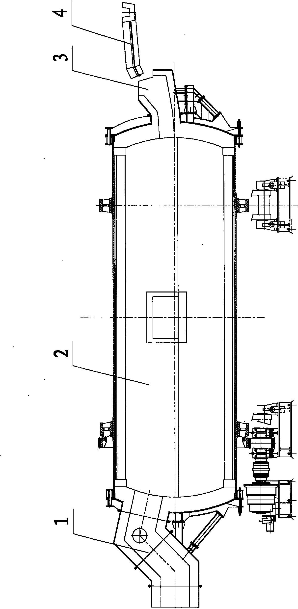
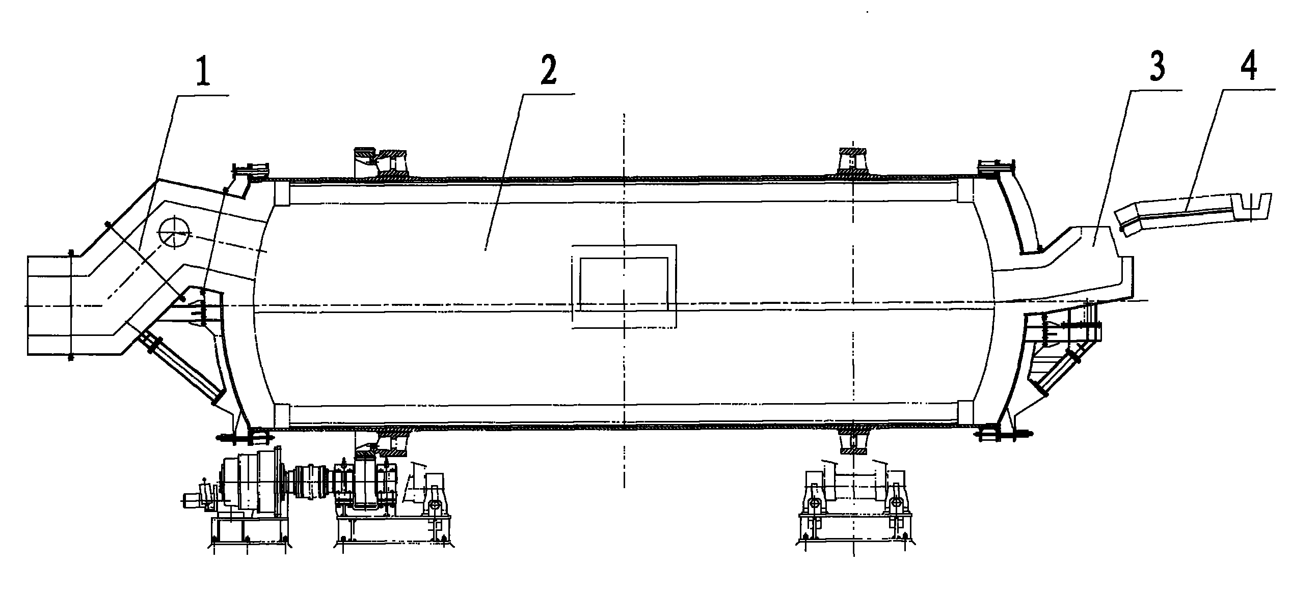
[0028] A feeding device for an anode refining furnace using a continuous copper blowing process, comprising a feeding port 3 of an anode refining furnace 2, a smoke exhaust port 1, and a connecting chute 4 arranged between the anode refining furnace and the blowing furnace. The height difference between the feed opening 3 and the copper opening of the blowing furnace is 2m, and it is connected with the connecting chute 4 .

[0029] The feeding port 3 is welded by steel plate, lined with refractory material, and fixed on the upper end wall of the anode refining furnace 2 with a bracket. One end wall, the feeding port 3 tilts along with the anode refining furnace 2. The smoke outlet 1 is directly connected to the inlet of the subsequent flue gas treatment system. The subsequent flue gas treatment system is a waste heat recovery boiler.

[0030] The feeding method of this specific embodiment one equipment is:

[0031] The hot blister copper blown by the converting furnace is d...

specific Embodiment approach 2

[0032] It is basically the same as Embodiment 1, except that the flue gas generated during the refining process is discharged from the exhaust port 1 of the side wall at the other end of the anode refining furnace 2, and enters the spray cooler for subsequent flue gas treatment.

specific Embodiment approach 3

[0033] It is basically the same as Embodiment 1, except that the flue gas generated during the refining process is discharged from the exhaust port 1 of the side wall at the other end of the anode refining furnace 2, and enters the secondary combustion chamber to be cooled by cold air for subsequent flue gas treatment.


PUM


Abstract

The invention discloses a feeding method and the feeding equipment of an anode refining furnace. Feeding is realized in a way that: through a connecting chute between a converting furnace and the anode refining furnace, hot crude copper produced by the converting furnace automatically flows into a feed inlet on the upper part of a headwall of the anode refining furnace due to an altitude difference between the converting furnace and the anode refining furnace, and then enters the anode refining furnace for refining. In the equipment, the feed inlet is fixedly arranged on the upper part of the headwall of the anode refining furnace by a bracket, aslant rotates with the anode refining furnace, forms the altitude difference of at least 1 cm with a copper placement opening of the converting furnace, and is jointed with the connecting chute. As the feed inlet and a smoke outlet are arranged on the two headwalls of the anode refining furnace respectively, the method has the advantages of low cost, small discharged smoke amount, high temperature and the favorability for waste heat recovery and treatment. The equipment has the characteristics of simple structure, low cost, secure operation, the capacity of avoiding the high-altitude lifting and delivery of high-temperature melt, high furnace sealing property, less air leakage, the favorability for flue gas waste heat recovery and subsequent flue gas treatment, and particular application to copper smelting plants adopting a copper continuous converting process.

Description

technical field [0001] The invention relates to an anode refining furnace, in particular to a charging method and equipment for an anode refining furnace. Background technique [0002] The feeding ports of the existing anode refining furnaces are all located at the top of the furnace body. Copper smelters that need to use continuous feeding for anode refining, if the feeding port is set at the top of the furnace body, and the flue gas is discharged from the feeding port at the same time as feeding, a fume collecting hood with complex structure and high cost needs to be installed above, and the feeding port and collecting A large amount of cold air will be sucked into the gaps of the fume hood, resulting in a large amount of exhausted flue gas. At the same time, the composition of the flue gas will be diluted, and the temperature of the flue gas will be reduced, which is not conducive to the recovery of waste heat of the flue gas and the treatment of the flue gas. Contents ...

Claims


Application Information

Patent Timeline
Patent Type & Authority Applications(China)
IPC IPC(8): F27D3/14
Inventor 姚素平袁剑平刘庆华廖文江
Owner CHINA NERIN ENG
Why Eureka
Try Eureka