
Boring device for cylinder hole of diesel engine stand

A cylinder hole and diesel engine technology, applied in boring/drilling, drilling/drilling equipment, boring bars, etc., can solve the problem of dimensional tolerances and geometric tolerances that do not meet the requirements, affecting the assembly accuracy of the whole machine, low efficiency, etc. problems, to achieve the effect of reducing processing costs, convenient detection, and simple adjustment

Inactive Publication Date: 2010-10-27
CSSC MARINE POWER
View PDF5 Cites 11 Cited by
  • Summary
  • Abstract
  • Description
  • Claims
  • Application Information

AI Technical Summary

Problems solved by technology

Due to the large diameter of the cylinder bore of the diesel engine frame and the large casting blank allowance, the traditional boring tool has insufficient rigidity of the boring bar, and the cutting resistance during boring will cause the boring tool to jump, resulting in inaccurate dimensional tolerances and shape and position tolerances of the cylinder bore. If it meets the requirements, it will affect the assembly accuracy of the whole machine and have a great impact on the normal operation of the diesel engine. It may even cause serious consequences of cylinder scuffing in the diesel engine. The cylinder bore processing is divided into three processes: rough, semi-finishing and finishing. Ordinary boring machines need to be replaced three times. Boring tool for processing, low efficiency

Method used


Image

  • Boring device for cylinder hole of diesel engine stand
  • Boring device for cylinder hole of diesel engine stand
  • Boring device for cylinder hole of diesel engine stand

Examples


Embodiment Construction

[0020] The present invention will be further described below in conjunction with drawings and embodiments.

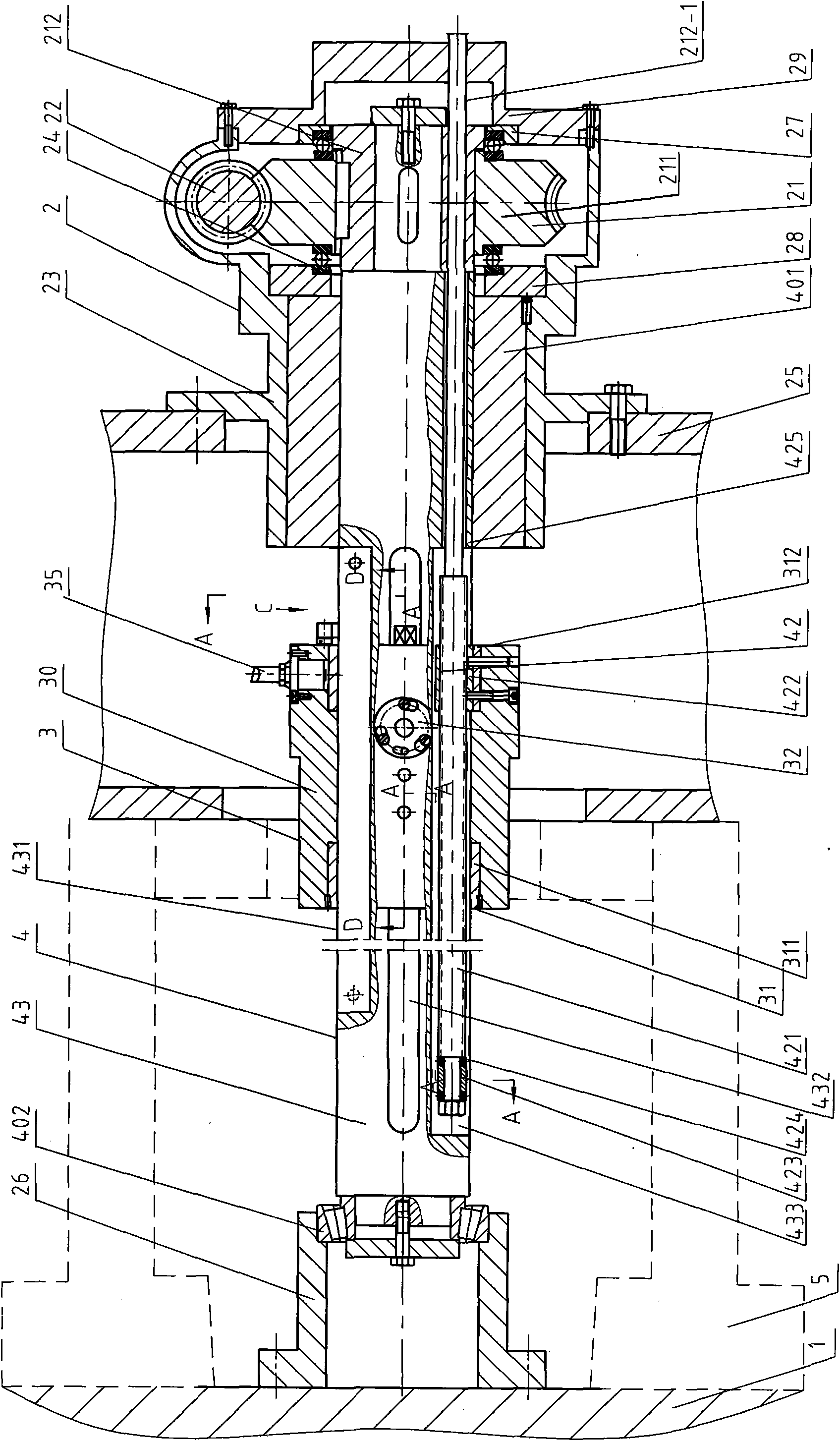
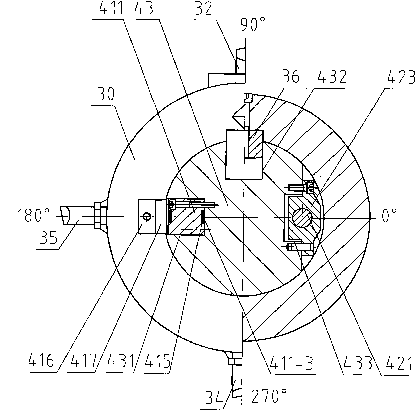
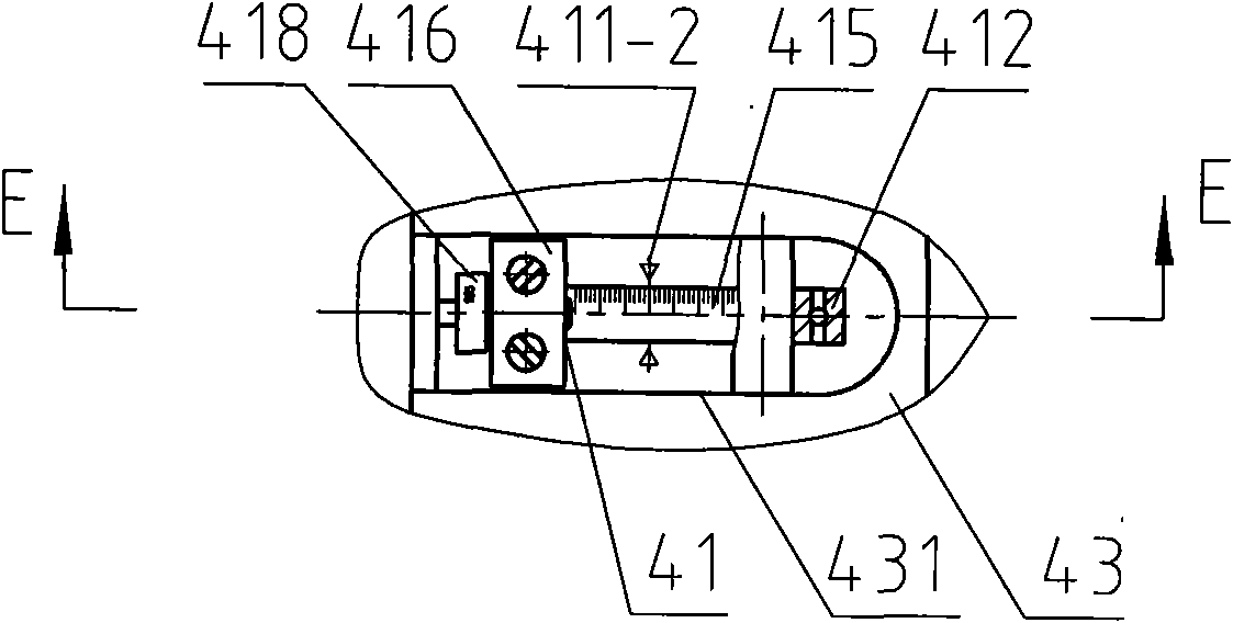
[0021] Such as figure 1 As shown, the present invention includes a boring bar transmission mechanism 2, a cutter body mechanism 3, and a boring bar mechanism 4. The boring bar transmission mechanism 2 is arranged on one end of a boring bar 43, and includes a worm wheel 21, a worm screw 22, a worm gear box 23, and a pair of supports Bearing 24, positioning frame 25, positioning seat 26. The worm wheel 21 of this embodiment is formed by fixedly connecting the wheel rim 211 and the wheel core 212. The wheel core 212 and the end of the boring bar 43 are fixedly connected by a flat key. 28. On the small retaining ring 27, the large retaining ring 28 and the small retaining ring 27 are respectively installed in the step holes on both sides of the worm gear casing 23, and the worm gear casing cover 29 is fastened on the outer end of the worm gear casing 23 by screws. The wor...


PUM


Abstract

The invention discloses a boring device for a cylinder hole of a diesel engine stand, which comprises a boring rod transmission mechanism, a boring rod mechanism and a cutter body mechanism, wherein the boring rod transmission mechanism is arranged on one end of a boring rod and comprises a worm gear, a worm, a worm gear case, a pair of supporting bearings, a positioning frame and a positioning seat; the worm gear is fixedly connected with the end of the boring rod; two sides of the worm gear are supported in one end of the worm gear case through the pair of supporting bearings and a retainer ring; the worm is arranged at one side of the worm gear; one end of the boring rod is supported in the other end of the worm gear case through a sliding bearing, and the other end of the boring rod is supported on a machine working table through a conical roller bearing and the positioning seat; the cutter body mechanism can axially move along the boring rod; and a screw rod transmission mechanism and a cutter body position measuring mechanism are also arranged in the boring rod. The invention can enable the cutter body mechanism to automatically and stably feed on the boring rod at constant speed to complete the boring of the cylinder hole, enables the cylinder hole of the diesel engine stand subjected to primary processing to meet the requirements on dimensional tolerance and perpendicularity tolerance of the cylinder hole, and can also measure the boring depth.

Description

technical field [0001] The invention relates to a boring device, in particular to a boring device for a diesel engine frame capable of measuring the depth of the boring, and belongs to the technical field of metal cutting. Background technique [0002] The diesel engine frame is the core component of the diesel engine. The cylinder liner is installed in the cylinder bore of the diesel engine frame, and the piston is installed in the cylinder liner. The machining tolerance and position tolerance of the cylinder bore are very demanding. Due to the large diameter of the cylinder bore of the diesel engine frame and the large casting blank allowance, the traditional boring tool has insufficient rigidity of the boring bar, and the cutting resistance during boring will cause the boring tool to jump, resulting in inaccurate dimensional tolerances and shape and position tolerances of the cylinder bore. If it meets the requirements, it will affect the assembly accuracy of the whole ma...

Claims


Application Information

Patent Timeline
Patent Type & Authority Applications(China)
IPC IPC(8): B23B41/00B23B29/02B23B29/03B23B47/02B23Q17/20
Inventor 史德明
Owner CSSC MARINE POWER
Learn More