Optoisolator for use in fiber-optic communication

An optical isolator and optical fiber communication technology, which is applied to instruments, optics, nonlinear optics, etc., can solve the problems of large volume, increase the length of the optical path, and unsatisfactory performance, and achieve the effect of short optical path and reducing temperature stability.

Inactive Publication Date: 2010-10-27
NAN TONG HUAWEI POWER EQUIP CO LTD +1
View PDF13 Cites 4 Cited by
  • Summary
  • Abstract
  • Description
  • Claims
  • Application Information

AI Technical Summary

Problems solved by technology

However, in this type of optical isolator, there is a lateral displacement between the exit position and the incident position of the beam, and the two orthogonally polarized light components need to be separated by a large distance in space, which not only increases the length of the optical path, but also easily introduces polarization

Method used


Image

  • Optoisolator for use in fiber-optic communication
  • Optoisolator for use in fiber-optic communication
  • Optoisolator for use in fiber-optic communication

Examples


Embodiment Construction

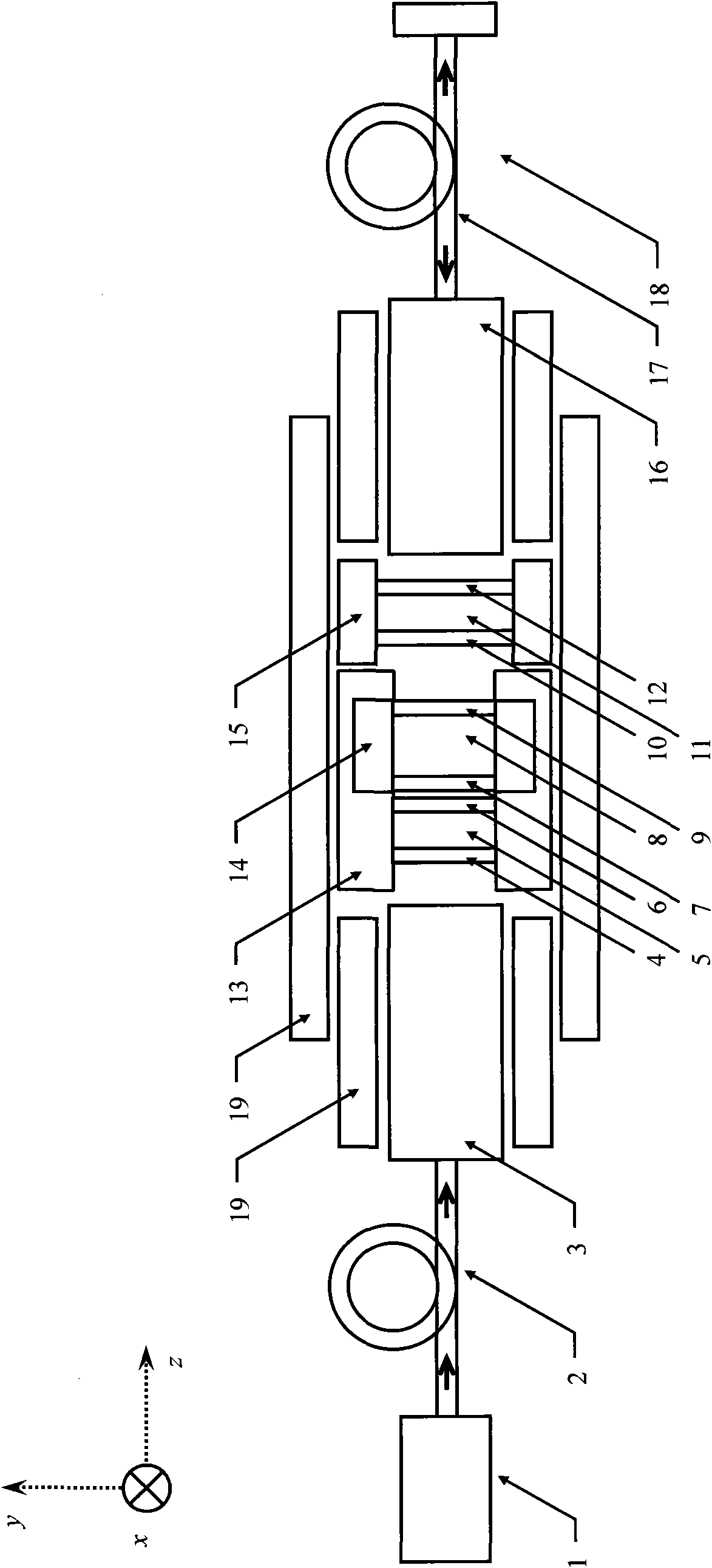
[0030] Now in conjunction with embodiment, accompanying drawing, the present invention will be further described:

[0031] see figure 1, the present invention is applied in the optical fiber communication system as an integrated device, including a laser 1, an incident optical fiber 2, a first fiber collimator 3, a first linear polarizer 4, a first quarter-wave plate 5, a first Antireflection coating 6, first high reflectivity reflector 7, Faraday rotator 8, second antireflection coating 9, second high reflectivity reflector 10, second quarter wave plate 11, second linear polarizer 12 , a support body 13, a permanent magnet 14, a micro-displacement device 15, a second fiber collimator 16, an outgoing fiber 17, a reflector 18 and a sleeve 19. The Faraday rotator 8 is placed inside the permanent magnet 14, and its magneto-optical material is selected from yttrium iron garnet crystal (YIG), which is coated with a reflective film with a reflectivity of 92% on the end face of the ...


PUM


Abstract

The invention relates to an optoisolator for use in fiber-optic communication, which is characterized in that: a positive polarization state control component, an insulator component and a negative polarization state control component are parallelly arranged along a light transmission direction in turn; the positive polarization state control component is comprised of a first linear polarizer and a first quarter wave plate, which are parallelly arranged along the light transmission direction in turn; the isolator component is comprised of a first high-reflectivity reflector, a Faraday rotator, a second high-reflectivity reflector and a permanent magnet, which are parallelly arranged along the light transmission direction in turn; and the negative polarization state control component is comprised of a second quarter wave plate and a second linear polarizer, which are parallelly arranged along the light transmission direction in turn. The optoisolator has the advantages that: the change in a Faraday rotation angle does not deteriorate the performance of the optoisolator seriously, so the requirements on the temperature stability of Faraday magneto-optic materials are lowered; a 40 to 65dB or above isolation degree requirement can be met by simply using single-stage isolation; and light beams do not displace transversely, the light path is short, and the miniaturization of elements can be realized.

Description

technical field [0001] The invention relates to an optical isolator for optical fiber communication, which is used to prevent light beams emitted by light-emitting devices such as lasers and optical amplifiers from returning to the light source after being reflected by the end faces of downstream optical elements. It can be used in optical fiber communication systems and belongs to laser, optical fiber communication technology field. Background technique [0002] In the optical fiber communication system, when the signal light emitted by the light-emitting device encounters the end face of the optical element in the downstream optical path, part of the light will be reflected back to the light source, resulting in broadening of the light source spectrum, increased noise, power instability, and performance degradation. In order to protect light-emitting devices such as lasers and optical amplifiers, eliminate unwanted reflected light waves, and ensure stable operation of the ...

Claims


Application Information

Patent Timeline
IPC IPC(8): G02F1/095
Inventor 底楠赵建林
Owner NAN TONG HUAWEI POWER EQUIP CO LTD
Why Eureka
Try Eureka