Coupled structure of passive mixer and active filter and receiver

A passive mixer and source filter technology, applied in the direction of logic circuit connection/interface layout, transmission system, electrical components, etc., can solve the problem of high power consumption, large receiver power consumption, and reduce the low cost of passive mixers Noise advantages and other issues to achieve the effect of reducing noise impact, overcoming high power consumption, and improving noise performance

Inactive Publication Date: 2010-10-27
广州市广晟微电子有限公司
View PDF4 Cites 5 Cited by
  • Summary
  • Abstract
  • Description
  • Claims
  • Application Information

AI Technical Summary

Problems solved by technology

[0004] However, there are at least the following disadvantages in the prior art: the function of the transimpedance amplifier is to convert the current signal output from the passive mixer into a voltage signal, and the series input resistance Rin will input the active The voltage signal of the source filter is converted into a current signal and input to the first-stage operational amplifier of the active filter. It can be seen that the conversion effect of the transimpedance amplifier is opposite to that of the series input resistance, and because in the prior art The thermal noise of the series input resistor Rin (also known as white noise, caused by the thermal shock of electrons in the conductor) accounts for more than 50% of the total noise at this level, therefore, the existence of thermal noise of the series input resistor Rin reduces The low noise advantage of passive mixer; In addition, in order to reach better linearity, and guarantee described passive mixer load low impedance, the operational amplifier in the described transimpedance amplifier needs to accomplish higher gain ( 60dB or more) and larger bandwidth (gain-bandwidth product above 1GHz), the improvement of gain and the increase of bandwidth require the operational amplifier to provide greater current (2mA), and the operational amplifier of high current has a large power consumption Disadvantages, so the power consumption of existing receivers is relatively large

Method used


Image

  • Coupled structure of passive mixer and active filter and receiver
  • Coupled structure of passive mixer and active filter and receiver
  • Coupled structure of passive mixer and active filter and receiver

Examples


Embodiment Construction

[0019] For reference and clarity, technical terms, abbreviations or abbreviations used hereinafter are summarized as follows:

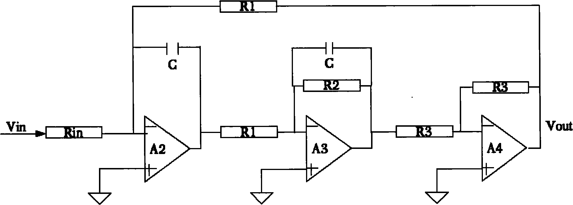
[0020] Biquad: A structural type of active filter.

[0021] The following will clearly and completely describe the technical solutions in the embodiments of the present invention with reference to the accompanying drawings in the embodiments of the present invention. Obviously, the described embodiments are only some, not all, embodiments of the present invention. Based on the embodiments of the present invention, all other embodiments obtained by persons of ordinary skill in the art without creative efforts fall within the protection scope of the present invention.

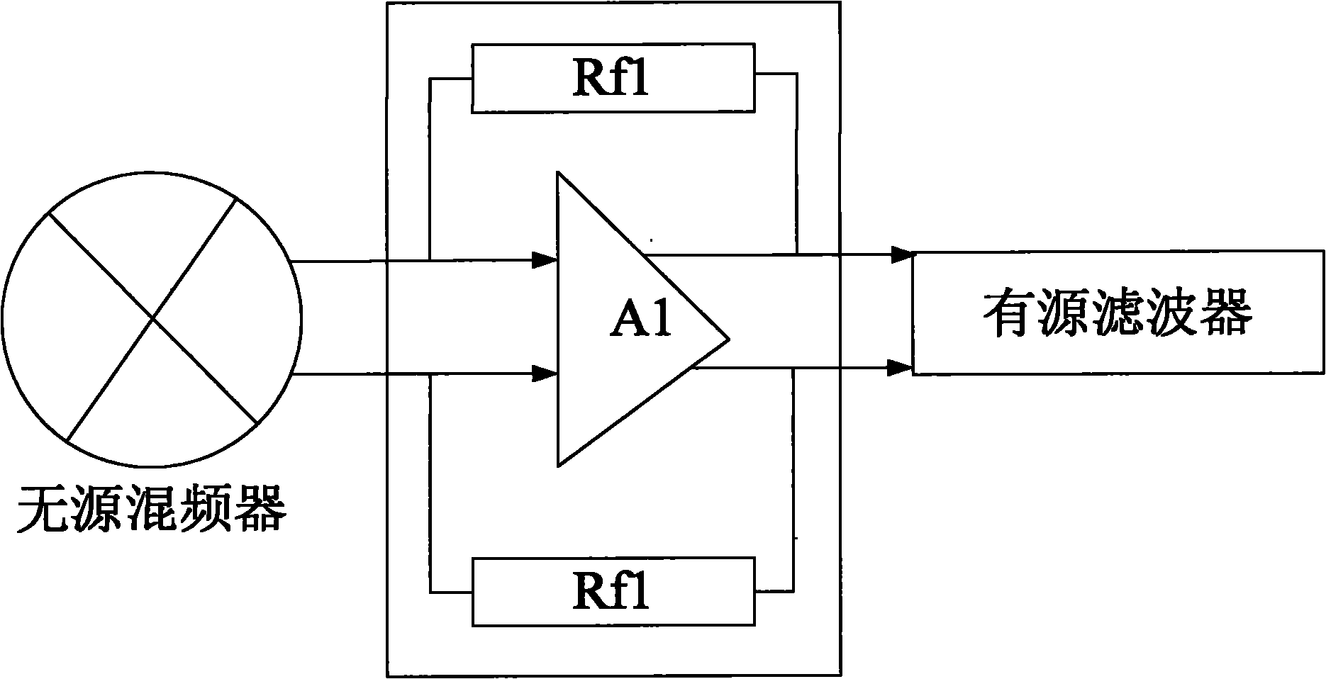
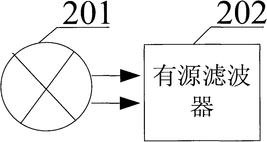
[0022] The invention provides a coupling structure of a passive mixer and an active filter and a receiver, so as to realize the purpose of improving the noise performance of the passive mixer and reducing the power consumption of the receiver.

[0023] First of all, it should be clear t...


PUM


Abstract

The embodiment of the invention discloses a coupled structure of a passive mixer and an active filter and a receiver. The coupled structure is characterized by directly coupling the output end of the passive mixer with the input end of a first-stage operational amplifier of the active filter. Relative to the prior art, the invention omits a transimpedance amplifier connected with the backward stage of the passive mixer and a serial input resistor in the active filter and reduces the noise influence caused by the serial input resistor and the transimpedance amplifier, thus improving the noise performance of the passive mixer and achieving the technical effect that the conversion gain of the passive mixer and the transmission characteristic of the active filter do not change. Besides, as the transimpedance amplifier is omitted, the invention overcomes the defect of high power consumption caused by large current of the transimpedance amplifier.

Description

technical field [0001] The invention relates to the technical field of wireless communication, more specifically, to a coupling structure of a passive mixer and an active filter and a receiver. Background technique [0002] In the receiving system of modern communication, the contradiction between the increasingly complex signal modulation and the increasing communication bit error rate is becoming more and more prominent, and the low noise and high linearity of the receiving system are therefore becoming more and more important. Therefore, based on passive The receiver of the mixer is more and more favored by people because of its lower flicker noise and higher linearity. [0003] In the prior art, passive mixers belong to current-driven mixers. As shown in FIG. An impedance amplifier, the function of the transimpedance amplifier is to convert the current signal output from the passive mixer into a voltage signal. The active filter is connected to the rear stage of the tr...

Claims


Application Information

Patent Timeline
Patent Type & Authority Applications(China)
IPC IPC(8): H03K19/0175H04B1/16
Inventor 黄沫
Owner 广州市广晟微电子有限公司
Why Eureka
Try Eureka