
Optical observation device of deformation in surrounding rock

An observation device and surrounding rock technology, applied in the direction of using optical devices, measuring devices, instruments, etc., can solve the problems of hindering the passage of vehicles and personnel, large errors in human readings, and difficult measurement, so as to save construction time and achieve high monitoring accuracy. High safety effect

Inactive Publication Date: 2010-11-17
INST OF ROCK AND SOIL MECHANICS - CHINESE ACAD OF SCI
View PDF9 Cites 15 Cited by
  • Summary
  • Abstract
  • Description
  • Claims
  • Application Information

AI Technical Summary

Problems solved by technology

There are some deficiencies in this type of technology and corresponding instruments and devices in practical applications: 1) It is necessary to manually approach the measuring hole for reading. 2) Personnel measurement requires assistance such as scaffolding, ladders or trolleys, which hinders the passage of vehicles and personnel during tunnel construction and affects normal construction
Therefore, in the construction of underground projects such as tunnels and mine roadways, there are many situations that should be used or not, and should be closely monitored, but they are mere formalities due to measurement difficulties.

Method used


Image

  • Optical observation device of deformation in surrounding rock
  • Optical observation device of deformation in surrounding rock
  • Optical observation device of deformation in surrounding rock

Examples


Embodiment Construction

[0014] Below in conjunction with accompanying drawing, the present invention is described in further detail:

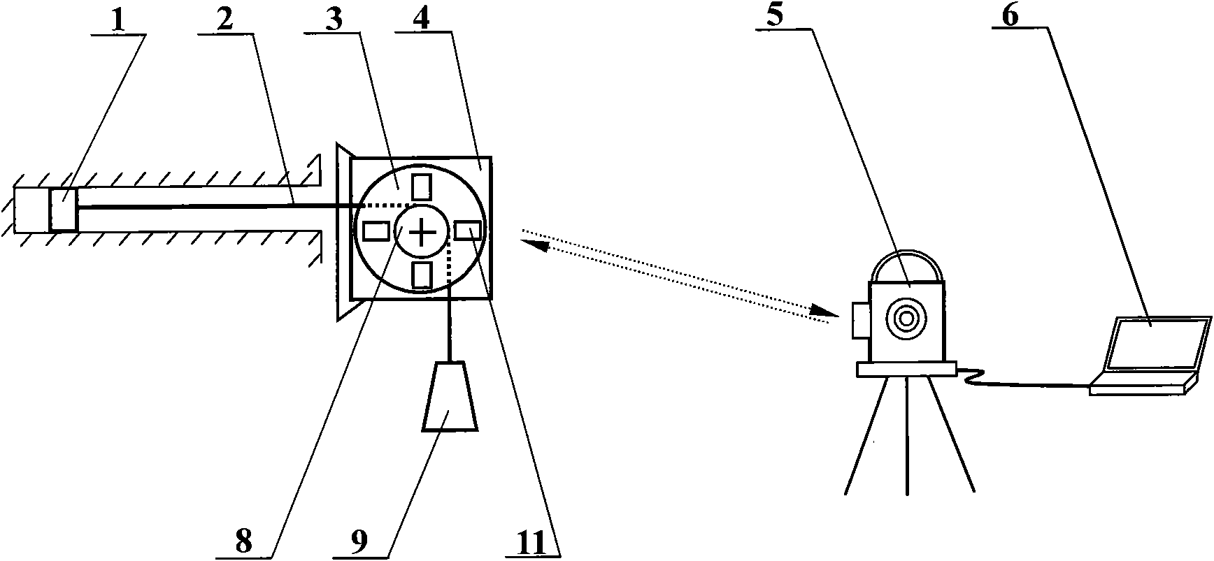
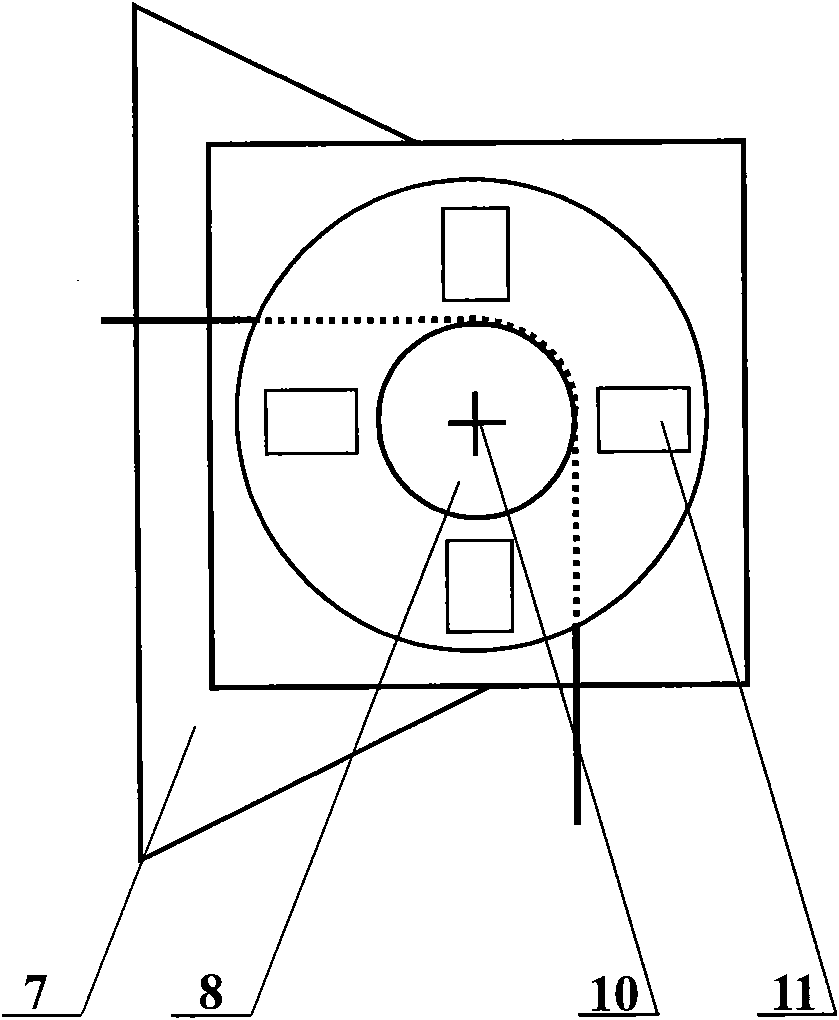
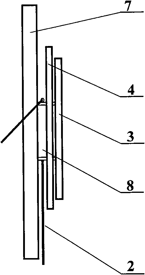
[0015] An optical observation device for internal deformation of surrounding rocks, consisting of a measuring point anchor head 1, a steel wire 2, a displacement turntable 3, a reflective film 4, a total station 5, a computer 6, an orifice bracket 7, a rotating shaft 8, a weight 9, a cross Logo 10 and window 11 are formed. It is characterized in that: the measuring point anchor head 1 is fixedly connected with the rock wall in the surrounding rock measuring borehole. The rotating shaft 8 is installed on the orifice bracket 7, the anchor head 1 of the measuring point is connected with the steel wire 2, the steel wire 2 bypasses the rotating shaft 8 and is connected with the weight 9, the displacement turntable 3 and the reflective film 4 are coaxially installed on the orifice bracket 7, The displacement turntable 3 covers the reflective film 4; the steel wire 2 is wou...


PUM

PropertyMeasurementUnit
Side lengthaaaaaaaaaa

Abstract

The invention discloses an optical observation device of deformation in a surrounding rock, which comprises a steel wire, a displacement rotating disc, a reflecting membrane, a total station, a computer, a rotating shaft and a heavy hammer, wherein an anchoring head of a measuring point is fixedly connected with the rock wall in a measuring drilled hole of the surrounding rock, the rotating shaft is mounted on an orifice support, the displacement rotating disc and the reflecting membrane are coaxially mounted on the orifice support, the displacement rotating disc covers the reflecting membrane, the steel wire is wound on the rotating shaft, the steel wire is connected with the heavy hammer, the reflecting membrane is fixedly connected with the orifice support, the total station is connected with the computer, analysis software is installed in the computer, and the reflecting membrane can reflect collimation laser emitted by the total station. Windows are uniformly and symmetrically distributed on the displacement rotating disc by taking the shaft line of the rotating shaft as the center of a circle. The device can observe the relative displacement of the measuring point in the surrounding rock in a far-distance, convenient and direct manner, and be conductive to fast measurement of the deformation of the underground engineering surrounding rock and the real-time analytical study of stability.

Description

technical field [0001] The invention relates to a surrounding rock deformation observation device, and more particularly relates to a device for optical observation of the internal deformation of the surrounding rock, which is suitable for deformation observation inside the surrounding rock in the excavation space of underground engineering such as tunnels and mine roadways. Background technique [0002] In recent years, my country's road and rail transportation, water conservancy and hydropower, urban subways and other major infrastructure constructions have flourished and developed rapidly, accompanied by the construction of a large number of tunnel projects (tunnels, underground caverns, underground workshops, and roadway networks). In the current tunnel construction in our country, the adoption of the new Austrian method is becoming more and more common, and a large amount of construction experience has been accumulated. In our country, it is often called the "anchor shot...

Claims


Application Information

Patent Timeline
IPC IPC(8): G01B11/16G01B11/02G01B11/26
Inventor 张程远刘小燕刘泉声
Owner INST OF ROCK AND SOIL MECHANICS - CHINESE ACAD OF SCI
Learn More