Wheel-type X-ray flaw detection robot device

A flaw detection device, X-ray technology, used in manipulators, material analysis using radiation, manufacturing tools, etc., to achieve the effects of high precision, reduced failure, and convenient operation

Inactive Publication Date: 2010-11-17
DONGDAN AOLONG RADIATIVE INSTR GRP
6 Cites 62 Cited by

AI-Extracted Technical Summary

Problems solved by technology

[0005] Aiming at the defects existing in the existing gamma source positioning non-destructive testing device, the p...

Method used

Lifting rod 4 is housed on fuel cell 3 right sides, and two forward-looking infrared cameras 1 are housed at lifting rod 4 tops, and two forward-looking infrared cameras 1 are installed opposite to each other, and GPS receiver is housed at lifting rod 4 tops Antenna 17 is equipped with main control computer 13, liquid crystal display 14, wireless image receiver 15, wireless data transmitter 16 on the right side of elevating mast 4 bottoms. The control part adopts the upper master computer, and the lower controller uses wireless long-distance data transmission and receiving equipment to complete the data exchange. When the master computer is connected to the Internet, you can also log in to the corresponding World Wide Web or WAP website through the remote computer and mobile phone. Query and set the working parameters of the linked robot. The establishment of the wireless long-distance data transmission link selects digital data transmission stations with better performance indicators, adopts digital signal processing, error correction coding, software radio, digital modulation and demodulation and surface mount integration technology, with high performance and high reliability specialty. The radio station provides a standard RS232 data interface, which can be directly connected to computers, data collectors, RTUs, PLCs, data terminals, GPS receivers, infrared cameras, etc. The transmission rate is from 9600 to 19200bps, and the bit error rate is lower than 10-6. The power is adjusted by software, any type of radio station can be set as the main station or remote station, and the non-transfer communication distance can reach 50km, which can adapt to the harsh indoor or outdoor working environment. The radio data and voice are compatible, can work in simplex, half-duplex, time-division duplex TDD, full-duplex mode, transmit and receive at the same frequency or different frequency transfer network, and have remote diagnosis, testing, monitoring functions to meet various appl...

Abstract

The invention relates to a wheel-type X-ray flaw detection robot device which comprises an X-ray flaw detection device, a remote wireless transmission device, a computer control device, a differential GPS (Global Positioning System), a fuel battery (or lead acid battery pack) and a robot body, wherein four infrared cameras are arranged on the robot body, and real-time images are remotely transmitted to an operator through video transmission equipment; a direct current voltage regulator is adopted in the controller of an X-ray generator; and the regulator is connected with an inverter by a tube voltage regulation knob, so that the tube voltage of the X-ray generator can be regulated. The operational control and operational state of the robot body are as follows: a digital data radio is adopted to transmit filed signals to an upper control computer; video signals are displayed on a display with visual display and convenient operation; isotope sources are not used, thereby meeting the requirement for environment protection; and a suspension system enables the robot body not to deflect and turn laterally on pipelines and rocks.

Application Domain

ManipulatorMaterial analysis by transmitting radiation

Technology Topic

VIT signalsVideo transmission +14

Image

  • Wheel-type X-ray flaw detection robot device
  • Wheel-type X-ray flaw detection robot device
  • Wheel-type X-ray flaw detection robot device

Examples

  • Experimental program(1)

Example Embodiment

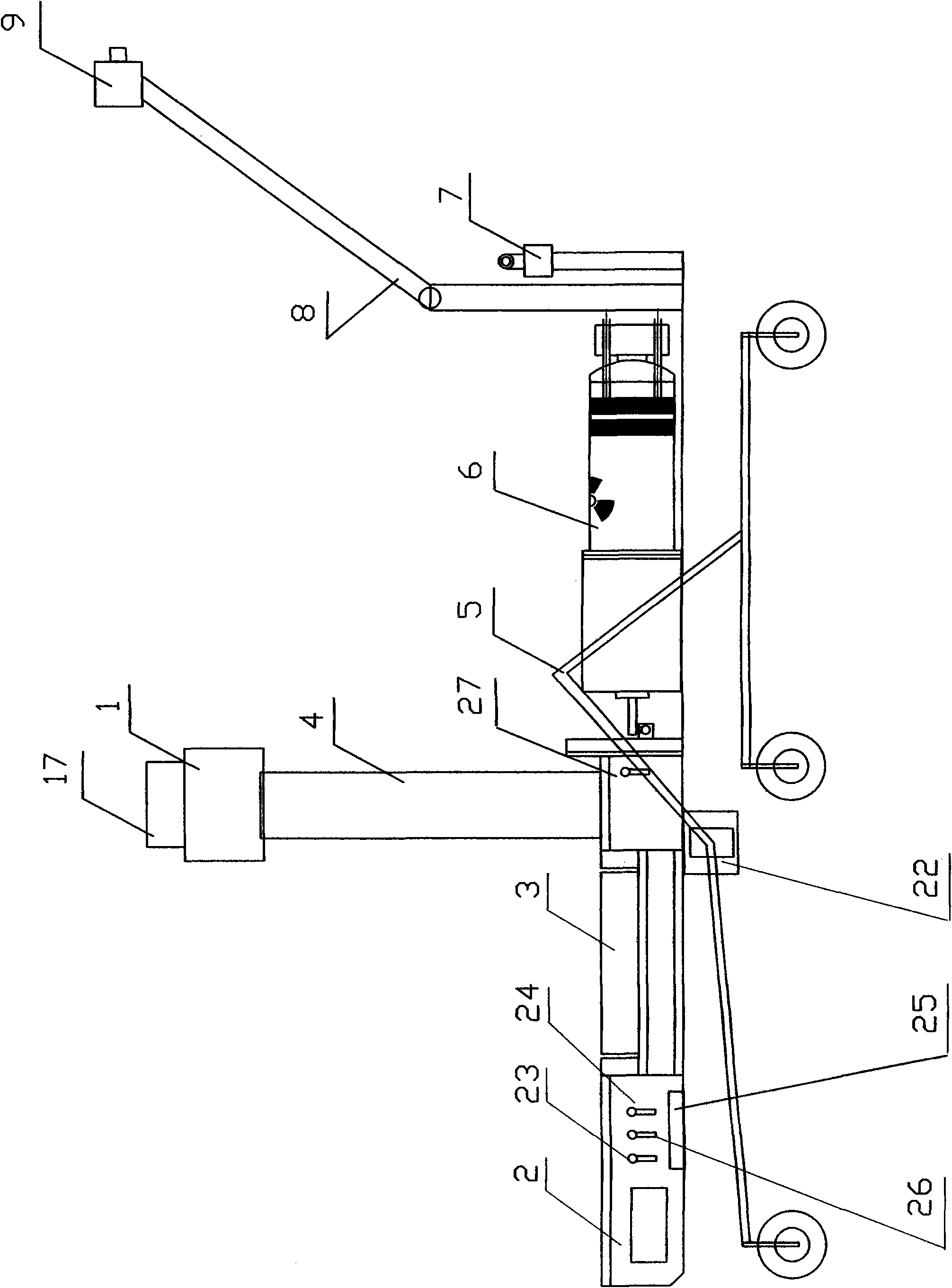
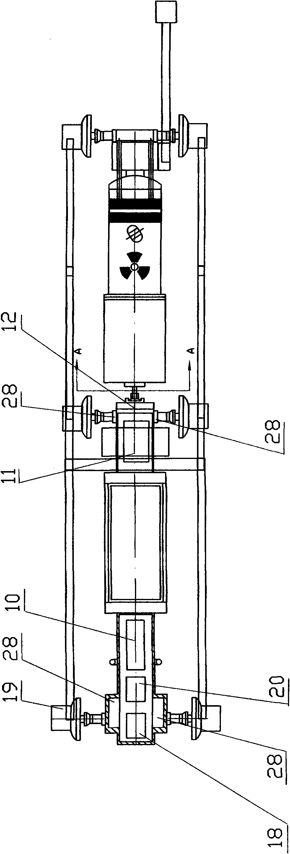
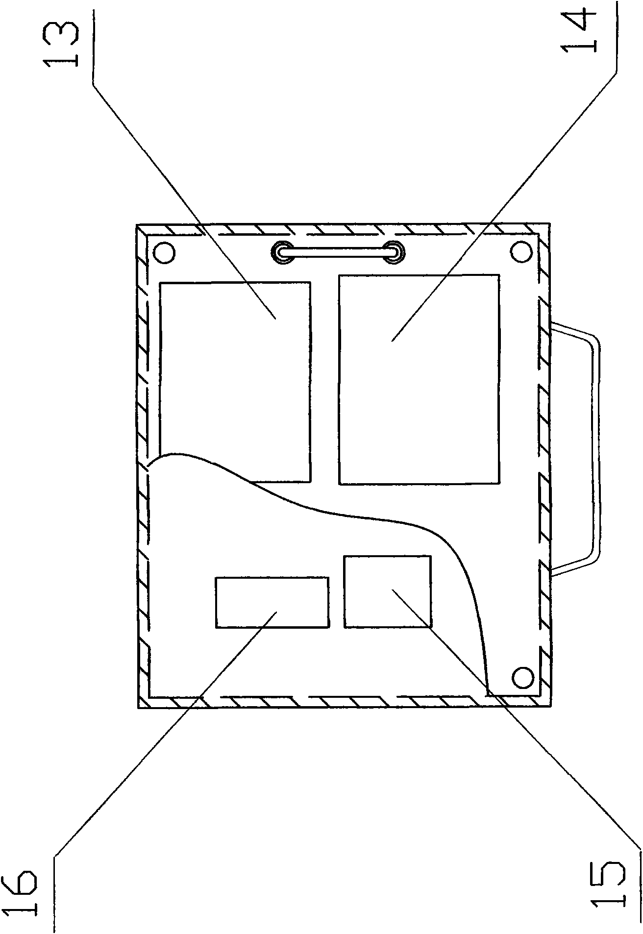
[0023] The structure and working principle of the present invention will be described in detail below with reference to the accompanying drawings.
[0024] A wheeled X-ray flaw detection robot device, such as figure 1 , figure 2 , image 3 As shown, the lifting mechanism 22 at the robot body is connected to the middle end of the suspension bracket 5. The lifting mechanism 22 is equipped with a suspension bracket 5 adjustment motor 12, and a servo motor 19 is installed on both sides of the front end of the suspension bracket 5. A running wheel 21 is installed on the upper part, and the same servo motor 19 and running wheel 21 as the front end are installed on both sides of the middle and rear ends of the suspension bracket 5. Due to the error of the robot's running wheel radius and the size of the robot's structure, sliding in motion, and ground fluctuations, the cumulative error is very large and cannot be positioned for a long time, so the six-wheel drive method is adopted, and each wheel has its own independent servo motor. . There is an independent steering engine 28 on the inner side of the two front-end running wheels and the two middle-end running wheel servo motors of the device. The steering engine can control any angle within 360 degrees. These four steering wheels can also make the robot suddenly turn and bend (turn into a bow). The suspension system of the running wheel is similar to the "rocker-bogie" system, and its function is to organically connect the running wheel and the robot body. In the old railway system, the "bogie" is a train wagon with six wheels that can rotate along a curved trajectory. This structure is introduced into the robot wheel suspension system. The "joystick" can ensure the balance of the robot body and can swing back and forth within the varying displacement between multiple wheels. The most important role of the suspension system is to adapt to sudden changes when the robot moves on the cylindrical pipe and the rocky terrain. If one wheel of the robot passes a protrusion in the pipe or a rock on the ground, one side of the robot will rise up, and the rocker of the robot's suspension system will turn the other side down or even beyond the center of the 6 wheels to keep the body balanced. This design can make the robot tilt 45 degrees in any direction without tipping over. However, when the robot's internal program detects that the tilt exceeds 30 degrees, the "error protection limit" is activated.
[0025] Servo motor driver 2 is installed on the robot body in order from the front to the back. The servo motor driver 2 is connected to the servo motor 19. Above the servo motor driver 2, there is an electronic compass 18, PLC controller 20, and wireless data transmitter 10. Temperature transmitter 23, pressure transmitter 24, gyroscope 25, humidity transmitter 26, power detection transmitter 27, the signal output and input cables of each detection and control instrument are connected to the main control computer 13, and the robot sensor part adopts Gyroscopes, accelerometers, infrared cameras, water probes, Hall sensors, sensors and transmitters to monitor the "health" of the robot's own temperature, humidity, pressure, and power, GPS satellite receiver modules and antennas, and electronic compasses and codes The multi-sensor system composed of the robot and the gyroscope is used as the positioning sensor of the robot, and the joint Kalman filter is used to fuse the multi-sensor information to locate the open-air robot and achieve high positioning accuracy. Since GPS cannot work normally indoors, the servo motor closed-loop system and gyroscope are used as the second positioning sensor to estimate the robot's speed, angle, and position information for indoor positioning. In the navigation system, the position of the robot can be determined by a computational positioning system (using a multi-sensor system composed of GPS satellite receiving modules and antennas, electronic compasses, encoders, and gyroscopes as the recording data of the robot's positioning and direction for calculation) or A closed-loop system composed of servo motors and encoders and a gyroscope are used to calculate the speed, angle and position of the robot, and to correct the value of the calculation method. Otherwise, the results of the calculation method cannot be used, and various electrical devices are connected to each other. Such as Figure 4 Shown.
[0026] A fuel cell 3 is installed on the right side of the gyroscope. There are no mechanical moving parts on the fuel cell structure, no noise in the power supply, and no harmful components in the reaction product water; the turnaround time is short, just refill the fuel; the service life is long, and the Feeding under any voltage does not affect the battery life; and because of its high power density, low operating temperature, high efficiency and other characteristics as the first choice.
[0027] A lifting rod 4 is installed on the right side of the fuel cell 3, two front-view infrared cameras 1 are installed on the top of the lifting rod 4, and the two front-view infrared cameras 1 are installed opposite to each other, and a GPS receiving antenna 17 is installed on the top of the lifting rod 4. A main control computer 13, a liquid crystal display 14, a wireless image receiver 15, and a wireless data transmitter 16 are installed on the right side of the lower part of the lifting rod 4. The control part adopts the upper host computer, and the lower controller uses wireless remote data transmission and reception equipment to complete data exchange. When the host computer is connected to the Internet, you can also log in to the corresponding World Wide Web or WAP website through the remote computer and mobile phone. Query and set the working parameters of the robots that have established links. The establishment of wireless long-distance data transmission link selects digital data transmission stations with better performance indicators, adopts digital signal processing, error correction coding, software radio, digital modulation and demodulation and surface mount integrated technology, with high performance and high reliability specialty. The radio provides a standard RS232 data interface, which can be directly connected to computers, data collectors, RTUs, PLCs, data terminals, GPS receivers, infrared cameras, etc. The transmission rate is from 9600 to 19200 bps, and the bit error rate is less than 10. -6 , The transmitting power is adjusted by software. Any type of radio station can be set as the main station or remote station. The communication distance without relay is up to 50km, which can adapt to the harsh indoor or outdoor working environment. Radio data and voice compatibility, can work in simplex, half-duplex, time-division duplex TDD, full-duplex mode, transmit and receive the same frequency or different frequency transfer network, and have remote diagnosis, testing, monitoring functions, to meet various applications Long-distance, high-speed, high-reliability data acquisition and control.
[0028] An X-ray generator 6 is installed on the right side of the control system device. The controller of the X-ray generator 6 is as Figure 5 As shown, a DC voltage regulator is used, and the regulator is connected to the inverter by a tube voltage adjustment knob, so that the tube voltage of the X-ray generator can be adjusted. A movable arm 8 is installed on the right side of the X-ray generator 6, a macro camera and a marking device 9 are installed at the end of the movable arm 8, and two rear-view infrared cameras 7 are installed on the right side of the movable arm 8, two rear-view cameras The infrared camera 7 is installed opposite to each other.
[0029] Four infrared cameras are installed on the robot body, and the real-time images are transmitted to the operator through a video transmission device. When the robot starts to run, the camera monitors the situation in the pipeline at any time, and transmits the information to the wireless image transmitter installed in the driving part, and the signal is transmitted and transmitted to the wireless image receiver of the controller, and displayed on the LCD The actual operation of the robot in the pipeline or outdoors. When reaching the pipeline weld inspection point, stop immediately and start exposure. 4 engineering obstacle avoidance infrared cameras to ensure visibility in the pipeline and at night. Two sets of two are installed on the front and rear of the robot. These cameras are used to create a three-dimensional image of the terrain within about 3 meters ahead. The created three-dimensional image can prevent the robot from getting lost or hitting an unknown object. Each camera has a viewing angle of approximately 120 degrees. The angle and height of the camera are simulating human eyes, so the image will be the same as seeing with your own eyes. The two cameras in the front are placed on the top of the robot's lifting mast, and the panoramic camera lifting mast device allows it to rotate 360 ​​degrees to obtain a panoramic view. The robot arm has 3 joints: shoulder, elbow and wrist. It is composed of servo motors and can operate the miniature camera to extend, bend and rotate to a certain angle. The end of the arm is a turret, shaped like a cross. The turret is similar to the structure of a human hand, which can operate a macro camera to provide images in the pipeline and other close distances, and can mark the defects found. When the sensor detects the same environment or the same property of the same object, the data provided by the sensor may be consistent or contradictory. If there is a contradiction, a system ruling is required. There are many ways of adjudication, such as weighted average method, decision method, etc.
[0030] Operating procedures such as Image 6 Shown: the data control link starts, the program enters the "system initialization" program, starts "read external input", reads the sensor data of each transmitter, then the program enters the "failure" judgment program, if there is a fault, then "Display the fault type", and then enter the "corresponding fault handling program", troubleshooting or judge no fault in the "fault" program, the program enters the "robot body send data" program to send various input signals to the control station, "Control station receives data and displays" data. When the data control link is started, the video acquisition link is started, the program enters the "system initialization" program, and then "sends the robot body image in real time", "control station receives the image" and "displays real-time environment", real-time environment information and control station At the same time, the received data is input into the program of "set system parameters according to status", the set system parameters are sent to the control station, and the control station is processed in the "control station sending operating data" according to the program and then output and sent to the computer through the wireless data transmitter for display Robot state, "The robot body receives data and responds", the program enters "Run to detection point", the video acquisition link returns, the data control link continues, "Trigger X-ray generator", "Film shooting to complete the work of a detection point" , "End a workflow."

PUM

no PUM

Description & Claims & Application Information

We can also present the details of the Description, Claims and Application information to help users get a comprehensive understanding of the technical details of the patent, such as background art, summary of invention, brief description of drawings, description of embodiments, and other original content. On the other hand, users can also determine the specific scope of protection of the technology through the list of claims; as well as understand the changes in the life cycle of the technology with the presentation of the patent timeline. Login to view more.

Similar technology patents

Graphene film and preparation method therefor

Owner:CHANGZHOU FUXI TECH CO LTD

Classification and recommendation of technical efficacy words

  • easy to operate
  • High precision

Lancet device

InactiveUS7303573B2inexpensively mass-producedeasy to operate
Owner:ABBOTT DIABETES CARE INC

Rapid and non-invasive optical detection of internal bleeding

InactiveUS20050065436A1easy to operaterapid and accurate result
Owner:HO WINSTON ZONH +2

Method for forecasting short-term power in wind power station

InactiveCN102102626AHigh precision
Owner:NORTH CHINA ELECTRIC POWER UNIV (BAODING) +1

Numerical control machine tool wear monitoring method

InactiveCN102091972AHigh precisionReal-time monitoring of tool wear
Owner:HUAZHONG UNIV OF SCI & TECH +1

Advertisement recommendation method and apparatus

ActiveCN104965890AHigh precisionPrecise screening
Owner:SHENZHEN TENCENT COMP SYST CO LTD
Why Eureka
Try Eureka