Hydrogen closed circulation system used for fuel cell

A fuel cell and circulation system technology, applied in the direction of fuel cells, fuel cell additives, fuel cell grouping, etc., can solve the problems of large power consumption, explosion, and large self-consumption power, and achieve the improvement of hydrogen cycle utilization rate and service life The effect of improving self-consumption power is small

Active Publication Date: 2010-11-17
SHANGHAI MUNICIPAL ELECTRIC POWER CO +1
View PDF0 Cites 26 Cited by
  • Summary
  • Abstract
  • Description
  • Claims
  • Application Information

AI Technical Summary

Problems solved by technology

[0014] 1. Use the hydrogen circulation pump to recycle excess hydrogen, but this method requires a powerful hydrogen circulation pump, and consumes a lot of power, noise, and self-consumption power;
[0015] 2. Frequent and intermittent hydrogen discharge, but this method is dangerous, if it encounters an open flame when discharging hydrogen, it will explode;
[0016] 3. The ejector pump is used to suck back excess hydrogen by forming a vacuum. However, when the amount of hydrogen entering the fuel cell stack is small, it is impossible to realize the ejection effect. composition ejection effect

Method used


Image

  • Hydrogen closed circulation system used for fuel cell
  • Hydrogen closed circulation system used for fuel cell

Examples


Embodiment 1

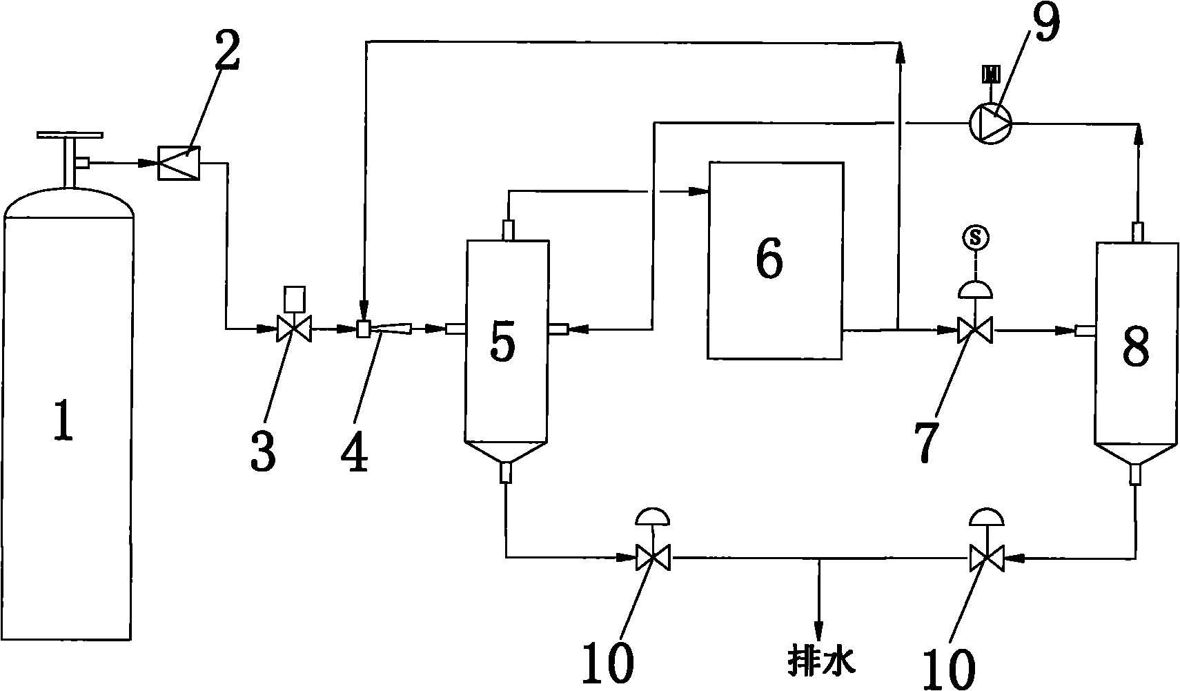
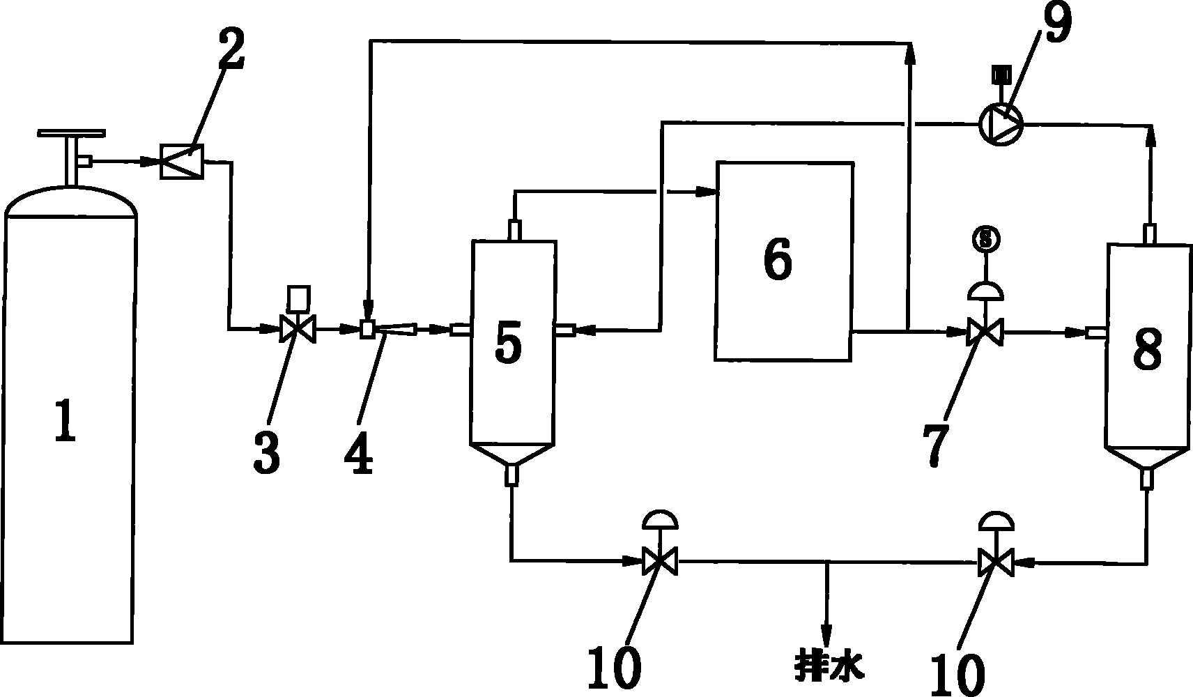
[0027] Such as figure 1 As shown, the hydrogen closed circulation system for 50KW fuel cell, the system includes hydrogen tank 1, pressure reducing valve 2, proportional switch solenoid valve 3, ejector pump 4, surge tank A5, fuel cell stack 6, hydrogen exhaust electromagnetic Valve 7, surge tank B8 and 200W diaphragm type hydrogen circulation pump 9, the hydrogen tank 1 is connected to the hydrogen inlet of the fuel cell stack 6 through the pressure reducing valve 2, the proportional switch solenoid valve 3, and the injection pump 4 in sequence, The hydrogen gas outlet of the fuel cell stack 6 is connected to the hydrogen exhaust solenoid valve 7, the surge tank A5 is arranged between the injection pump 4 and the hydrogen gas inlet of the fuel cell stack 6, and the pressure surge tank B8 is connected to the hydrogen exhaust solenoid valve 7. The hydrogen circulation pump 9 is respectively connected to the surge tank A5 and the surge tank B8. After the hydrogen comes out of th...


PUM


Abstract

The invention relates to a hydrogen closed circulation system used for a fuel cell. The system comprises a hydrogen tank, a pressure-reducing valve, a ratio switch solenoid valve, an ejector pump, a fuel cell stack, a hydrogen discharging solenoid valve, a hydrogen circulation pump and voltage-regulation tanks (A,B), wherein the hydrogen tank is connected to the hydrogen inlet of the fuel cell stack through the pressure-reducing valve, the ratio switch solenoid valve and the ejector pump sequentially; the hydrogen outlet of the fuel cell stack is connected with the hydrogen discharging solenoid valve; the voltage-regulation tank A is arranged between the ejector pump and the hydrogen inlet of the fuel cell stack; the voltage-regulation tank B is connected with the hydrogen discharging solenoid valve; the hydrogen circulation pump is connected with the voltage-regulation tanks (A,B) respectively; hydrogen enters the voltage-regulation tank A for water vapor separation and then enters the fuel cell stack for reaction; excessive hydrogen is discharged to the voltage-regulation tank B by the hydrogen discharging solenoid valve; and the hydrogen in the voltage-regulation tank B is returned to the voltage-regulation tank A by the hydrogen circulation pump. Compared with the prior art, the hydrogen closed circulation system has the advantages of small self-consuming power, high hydrogen utilization ratio and the like.

Description

technical field [0001] The invention relates to a fuel cell, in particular to a hydrogen closed circulation system for the fuel cell. Background technique [0002] An electrochemical fuel cell is a device that converts hydrogen and oxidants into electrical energy and reaction products. The internal core component of the device is the membrane electrode (Membrane Electrode Assembly, referred to as MEA). The membrane electrode (MEA) is composed of a proton exchange membrane and two porous conductive materials, such as carbon paper, sandwiched between the two sides of the membrane. On the two boundary surfaces of the membrane and the carbon paper, there are even and finely dispersed catalysts for initiating electrochemical reactions, such as metal platinum catalysts. Conductive objects can be used on both sides of the membrane electrode to draw the electrons generated during the electrochemical reaction through an external circuit to form a current loop. [0003] At the anode...

Claims


Application Information

Patent Timeline
Patent Type & Authority Applications(China)
IPC IPC(8): H01M8/04H01M8/24H01M8/04089H01M8/2457
CPCY02E60/50
Inventor 胡里清王泽民
Owner SHANGHAI MUNICIPAL ELECTRIC POWER CO
Why Eureka
Try Eureka