Method and system for improving dynamic range in RF system

A dynamic range and power divider technology, applied in transmission systems, electrical components, etc., can solve the problems of shortening the communication range, no gain, reducing the signal-to-noise ratio of the received signal, etc., to improve the dynamic range and sensitivity, reduce adverse effects, The effect of suppressing radio frequency interference

Inactive Publication Date: 2013-04-10
NINGBO CHENGDIAN TAIKE ELECTRONICS INFORMATION TECH DEV
View PDF4 Cites 0 Cited by
  • Summary
  • Abstract
  • Description
  • Claims
  • Application Information

AI Technical Summary

Problems solved by technology

Due to the large signal amplitude of the signal f1, the reflected echo of the short-distance obstacle is about 30dB lower than the transmitted wave, usually more than 20dB higher than the signal f2, which will reduce the performance of the receiver. The specific performance is: 1. Reduce the received signal The signal-to-noise ratio also reduces the receiving sensitivity of the receiver and shortens the range of communication; 2. Increases the range of signal changes and reduces the dynamic range of useful signals
3. It is easy to cause the low noise amplifier in the receiver to be saturated and have no gain, reduce the reliability of the receiver or even burn the receiver
Reduced detection capability of small target signals
4. Intermodulation signals are generated, which increases interference and system power consumption
[0004] There are several defects in the previous processing method. 1. The echo signal has a large range of changes, and the system requires a large number of ADs, which increases the signal processing burden of the system and increases the system cost.
2. Using a low noise amplifier with a high 1dB compression point alleviates the saturation pressure of the pre-stage low noise amplifier to a certain extent, but does not solve the problem of signal dynamic range
3. Often only focus on the leakage of the transmitted signal, while ignoring the strong reflection signal of close-range obstacles

Method used


Image

  • Method and system for improving dynamic range in RF system
  • Method and system for improving dynamic range in RF system
  • Method and system for improving dynamic range in RF system

Examples


Embodiment 1

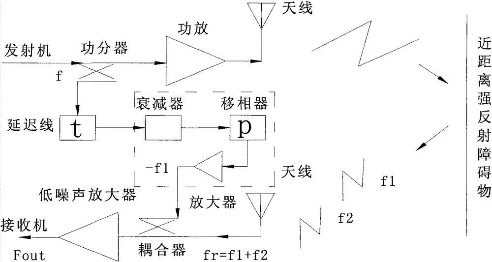
[0018] Example 1: figure 2 It is a system block diagram of the present invention, and the system for improving the dynamic range in an RF system includes a transmitter, a power divider, a power amplifier, an antenna, a coupler, a low-noise amplifier, a receiver, a delay line, a phase shifter, an attenuator and amplifier. The transmitter, the power splitter, the power amplifier, and the antenna are sequentially connected, the antenna, the coupler, and the low-noise amplifier are sequentially connected, and the power splitter, the delay line, the attenuator, the phase shifter, the amplifier, and the coupler are sequentially connected. The power divider divides the power of the transmitter into a part of the signal, and after adjusting the amplitude, phase and delay time of the delay line, attenuator, phase shifter and amplifier, the signal -f1 is obtained, and then sent to the low-noise receiver through the coupler amplifier. Most of the signal from the transmitter is amplifi...

Embodiment 2

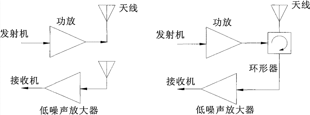
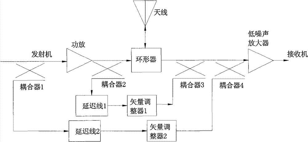
[0031] Embodiment 2 differs from Embodiment 1 in that: Embodiment 1 uses a dual-antenna system for transmitting and receiving, and the coupling between the antennas ensures the isolation of transmitting and receiving. Embodiment 2 uses an isolator to realize the isolation of transmitting and receiving. Usually, a similar technical principle is adopted to improve the system transceiver isolation.

[0032] The invention suppresses the radio frequency interference caused by short-distance reflection by adding a delay line and a vector adjuster in the system, thereby reducing its bad influence on the receiving system. The method adopted in the present invention suppresses the radio frequency interference in the receiving system by coupling the transmitting signal and adjusting the vector, and can be widely used in systems such as continuous wave radar and RFID, and has good application prospects.


PUM


Abstract

The invention discloses a method and a system for improving a dynamic range in an RF system. In the system, an emitter, a power distributor, an amplifier and antenna are connected in turn, the antenna, a coupler, a low noise amplifier and a receiver are connected in turn, and a delay line and a vector regulator are connected between the power distributor and the coupler; the output end or input end of the power amplifier is connected with the input end of the delay line through the power distributor, and the output ends of the delay line and the vector regulator are connected with the input end of the low noise amplifier through the coupler; the power distributor is used for coupling part of carrier signals f; and the vector regulator is used for regulating the amplitudes of coupled carrier signals f and inverting the coupled carrier signals to obtain signals f1. The method and the system have the advantages that: firstly, a pre-feeding back method is used to inhibit radio frequency interference to a maximum degree; secondly, the amplitude of interference signals is lowered, the signal-to-noise ratio is improved, the dynamic range and sensitivity of a receiving system are improved; and thirdly, the structure is simple and easy to realize.

Description

technical field [0001] The invention mainly relates to a continuous wave radar, RFID and other transceiver systems, and mainly relates to a method and a system for improving the dynamic range in the RF system. Background technique [0002] Continuous wave radar, RFID and other transceiver systems usually use circulators as transceiver isolation devices, but the isolation of circulators is limited, and it is easy to cause excessive leakage of transmitted signals into the receiving path. Therefore, dual antenna technology is usually used to reduce the leakage in the receiving path Signal. Even so, there is still a major technical problem in the transceiver system, which is the interference of short-distance obstacles, such as radome. [0003] Since both continuous wave radar and RFID system use continuous wave to transmit signals, the received signals not only include the interference f1 of short-distance strong reflection targets, but also include the reflection signals f2 a...

Claims


Application Information

Patent Timeline
Patent Type & Authority Patents(China)
IPC IPC(8): H04B1/10H04B1/12
Inventor 唐伟曾志毅梁刘永钱可伟
Owner NINGBO CHENGDIAN TAIKE ELECTRONICS INFORMATION TECH DEV
Why Eureka
Try Eureka