Special metal resistance rivet welding device

A technology of dissimilar metals and resistance, applied in the field of dissimilar metal resistance riveting welding devices, can solve the problems of inability to soften materials, and achieve the effects of avoiding riveting cracks and brittle cracks and reducing riveting force

Inactive Publication Date: 2010-11-24
SHANGHAI JIAO TONG UNIV +1
View PDF11 Cites 33 Cited by
  • Summary
  • Abstract
  • Description
  • Claims
  • Application Information

AI Technical Summary

Problems solved by technology

However, this method is a unilateral connection process, which is only suitable for the connection between tubular structural parts with high rigidity and plates. It is difficult to use for the connection of plates that account for the main component types in the body-in-white structure due to the low o

Method used


Image

  • Special metal resistance rivet welding device
  • Special metal resistance rivet welding device
  • Special metal resistance rivet welding device

Examples


Embodiment 1

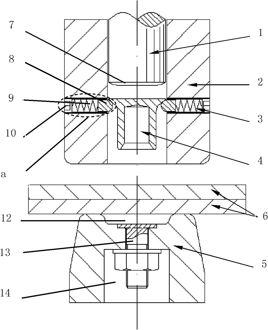
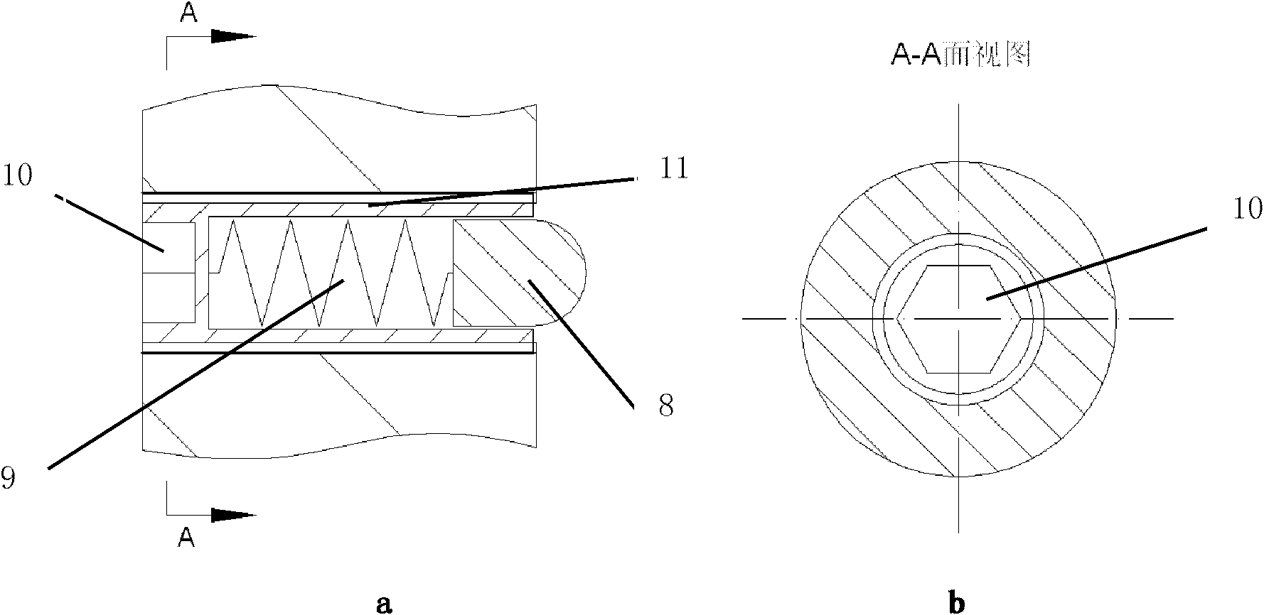
[0029] Such as figure 1 As shown, this embodiment includes: impact electrode 1, blank holder 2, spring bead positioning mechanism 3, semi-hollow rivet 4 and ring electrode 5, wherein: blank holder 2, plate to be welded 6 and ring electrode 5 are sequentially arranged from the top In the lower setting, the impact electrode 1 is sleeved in the blank holder 2, four spring bead positioning mechanisms 3 are distributed radially and horizontally in the blank holder 2, and the semi-tubular rivet 4 is vertically placed in the blank holder 2 and connected to the blank holder 2. The spring bead positioning mechanism 3 is in contact with each other, and the impact electrode 1, the semi-hollow rivet 4 and the ring electrode 5 are coaxially arranged.

[0030] A truncated cone 7 with an inclination angle of 10° is provided on the side of the bottom of the impact electrode 1 facing the semi-tubular rivet 4 to provide the current density required by the process.

[0031] The blank holder 2 i...

Embodiment 2

[0055] The plate 6 to be welded in this embodiment is: high-strength steel DP780 + aluminum alloy AA6061-T6, that is, the high-strength steel is on top and the aluminum alloy is on the bottom; the thickness of the plates is matched: 1.4mm+2mm.

[0056] The semi-hollow rivet 4 adopts the traditional self-piercing riveting countersunk head rivet, the head diameter is 7.8mm, the leg outer diameter is 5.3mm, and the rivet length is 7mm. The material is boron-treated high-strength steel, and the surface is coated with 12μm zinc-tin alloy plating.

[0057] Process parameters: the riveting speed of the impact electrode 1 is 40mm / s, the pre-pressing displacement is 1mm, the riveting current is 1.5kA DC, the brazing current is 5kA, the power-on time is 100ms, and the holding time is 40ms. The process curve is as follows Figure 5 (b) shown.

[0058] Other implementation modes of this embodiment are the same as Embodiment 1.


PUM

PropertyMeasurementUnit
Diameteraaaaaaaaaa
Lengthaaaaaaaaaa
Diameteraaaaaaaaaa

Abstract

The invention discloses a special metal resistance rivet welding device, which belongs to the technical field of automobile manufacturing. The special metal resistance rivet welding device comprises an piercing electrode, a blank holder, a plurality of spring bead positioning mechanisms, a semi-hollow rivet and an annular electrode, wherein the blank holder, a to-be-welded plate and the annular electrode are arranged in turn from top down; the piercing electrode is sleeved in the blank holder; the plurality of spring bead positioning mechanisms are horizontally arranged in the blank holder along a radial direction; the semi-hollow rivet is vertically arranged in the blank holder and is contacted with the spring bead positioning mechanisms; and the piercing electrode, the semi-hollow rivet and the annular electrode are arranged coaxially. In the invention, based on the mechanical connection of the self-piercing riveting process of the semi-hollow rivet, the resistance heat generation mechanism of resistance spot welding is introduced, the softening of plates by resistance heat eliminates riveting cracks and brittle fractures, reduces riveting force and increases the mechanical locking between the rivet and a lower-layer plate, the soldered connection between the rivet and plate pieces is realized by resistance heat, mechanical-solid phase double connection is formed finally and the reliability and connection strength of an adapter are improved.

Description

technical field [0001] The invention relates to a welding device in the technical field of automobile manufacturing, in particular to a resistance riveting welding device for dissimilar metals. Background technique [0002] Since the density of non-ferrous metals and their alloys such as aluminum and magnesium is much lower than that of steel, they are favored by major automobile manufacturers. However, the overall mechanical properties of advanced steel are still better than the above-mentioned non-ferrous alloy materials. Therefore, non-ferrous alloys and advanced high-strength The joint application of steel will be the general trend of future body assembly manufacturing. Due to the huge difference between the melting point and thermal expansion coefficient of non-ferrous alloys and high-strength steels and the formation of hard and brittle phases-intermetallic compounds during welding, it is difficult to realize the connection between non-ferrous alloys and high-strength ...

Claims


Application Information

Patent Timeline
IPC IPC(8): B23K11/00B23K11/20
CPCB21J15/025B21J15/08B21J15/285B21J15/32B21J15/36
Inventor 林忠钦来新民李永兵楼铭王培中陈关龙
Owner SHANGHAI JIAO TONG UNIV
Why Eureka
Try Eureka