
Collision ionization type field effect transistor of sinking channel and manufacture method thereof

A field-effect transistor, impact ionization technology, applied in semiconductor/solid-state device manufacturing, circuits, electrical components, etc., can solve problems such as limiting the switching speed of transistors, and achieve the effect of reducing SS value, increasing switching speed, and increasing device frequency.

Inactive Publication Date: 2012-08-22
FUDAN UNIV
View PDF0 Cites 0 Cited by
  • Summary
  • Abstract
  • Description
  • Claims
  • Application Information

AI Technical Summary

Problems solved by technology

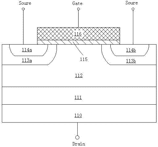
[0005] However, since both UMOSFET and IGBT adopt a gate-controlled n-p-n or p-n-p structure, their minimum subthreshold swing (SS) is limited to 60mv / dec, which limits the switching speed of the transistor

Method used


Image

  • Collision ionization type field effect transistor of sinking channel and manufacture method thereof
  • Collision ionization type field effect transistor of sinking channel and manufacture method thereof
  • Collision ionization type field effect transistor of sinking channel and manufacture method thereof

Examples


Embodiment Construction

[0047] Exemplary embodiments of the present invention will be described in detail below with reference to the accompanying drawings. In the drawings, the thicknesses of layers and regions are exaggerated for convenience of illustration, and the shown sizes do not represent actual sizes. The referenced figures are schematic illustrations of idealized embodiments of the invention, and the illustrated embodiments of the invention should not be construed as limited to the particular shapes of regions illustrated in the figures but are to include resulting shapes, such as manufacturing-induced deviations. For example, the curves obtained by etching are usually curved or rounded, but in the embodiment of the present invention, they are all represented by rectangles. The representation in the figure is schematic, but this should not be considered as limiting the scope of the present invention. Also in the following description, the terms wafer and substrate used may be understood to ...


PUM


Abstract

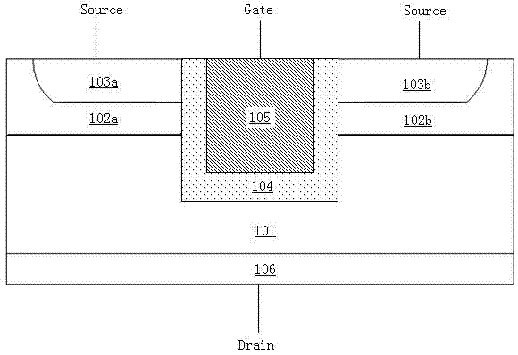
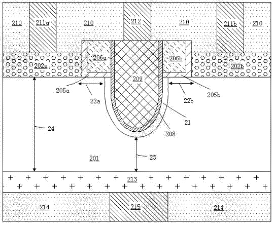
The invention belongs to the technical field of power semiconductor devices, and in particular relates to a collision ionization type field effect transistor of a sinking channel and a manufacture method thereof. The collision ionization type field effect transistor comprises a semiconductor substrate, a drain region positioned at the bottom of the substrate and provided with a first doping type,a groove structure positioned in the substrate, a grid electrode covering in the groove, a dielectric layer positioned between the grid electrode and the semiconductor substrate, a source region positioned at both sides of the groove and the top of the substrate and provided with a second doping type, and an insulation dielectric layer positioned between the groove and the source region. The use of the sinking type channel structure and the collision ionization working principle ensures that the transistor can improve drive current while inhibiting a subthreshold oscillation range so as to further improve the switching speed and the response frequency of a device and simultaneously reduce the off-state power consumption of the device. The field effect transistor is very suitable for the manufacture of integrated circuit chips, particularly the manufacture of the high-speed high-power chips.

Description

technical field [0001] The invention belongs to the technical field of power semiconductor devices, and in particular relates to a power semiconductor field effect transistor and a manufacturing method thereof, in particular to an impact ionization field effect transistor with a recessed channel and a manufacturing method thereof. Background technique [0002] Power semiconductor devices are the internal driving force of the continuous development of power-electronic systems, especially in terms of energy saving, dynamic control, noise reduction, etc., and have irreplaceable effects. Power semiconductors are mainly used to control the energy transfer between the energy source and the load, and have the characteristics of high precision, fast speed and low power consumption. In the past 20 years, power devices and their packaging technology have developed rapidly, especially power MOS transistors, which have replaced traditional bipolar transistors in many application fields ...

Claims


Application Information

Patent Timeline
Patent Type & Authority Patents(China)
IPC IPC(8): H01L29/78H01L29/10H01L29/423H01L21/336
Inventor 臧松干刘昕彦王鹏飞张卫
Owner FUDAN UNIV
Learn More