Superconducting energy storage impulse power electrical source

A technology of pulse power and superconducting energy storage, applied in the field of pulse power, can solve the problems of superconducting energy storage inductance, large system scale, large quench resistance, etc., and achieve high pulse current, reduce volume and weight, and large The effect of pulse current output

Inactive Publication Date: 2010-11-24
SOUTHWEST JIAOTONG UNIV
View PDF3 Cites 16 Cited by
  • Summary
  • Abstract
  • Description
  • Claims
  • Application Information

AI Technical Summary

Problems solved by technology

But there are the following disadvantages: 1. The energy storage density of the capacitor is not high, it is difficult to reduce the volume of the pulse power supply; 2. And the capacitor cannot store energy for a long time, and the energy storage effect is not good
The problem with it is that if you want to get a very high amplitude pulse current, you need to superimpose a lot of superconducting energy storage inductors, which makes the system very large in scale
Its problems are: 1. Repeated use of superconducting energy storage inductance quenching will reduce the service life of superconducting energy storage inductance; The primary winding of the pulse transformer, which is not conducive to the improvement of the transformer coupling coefficient, will also reduce the output efficiency of the power supply; 3. To obtain a large pulse current output under the condition of a large transformer ratio, a very large quench resistance is required , which puts higher requirements on the material properties of superconductors and quench triggering technology;
There is also a prominent problem in this mode that when the superconducting energy storage inductor discharges the pulse transformer, it will generate a high pulse voltage, which has very high requirements for the disconnect switch, and the output efficiency of this circuit mode is low.

Method used


Image

  • Superconducting energy storage impulse power electrical source
  • Superconducting energy storage impulse power electrical source
  • Superconducting energy storage impulse power electrical source

Examples


Embodiment Construction

[0017] The present invention will be further described below with reference to the drawings and embodiments.

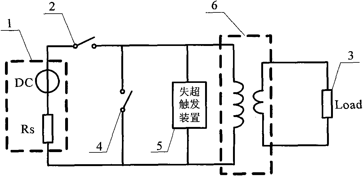
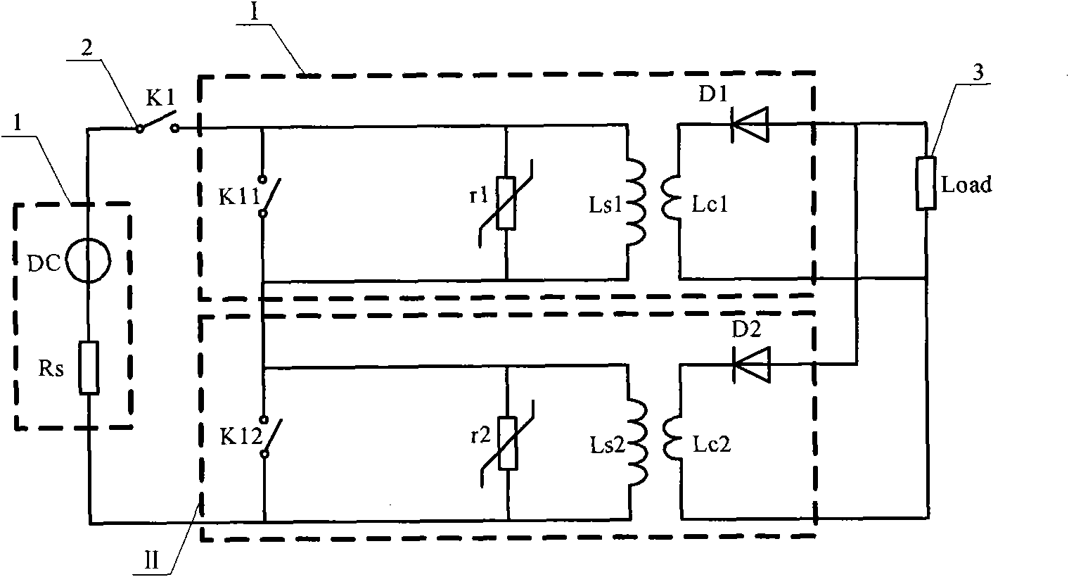
[0018] As attached figure 2 As shown, a superconducting energy storage pulse power supply circuit includes an initial charging power supply (1), a power switch (2), a module I, a module II, and a load (3). The modular power supply circuit can be composed of multiple modules. For the sake of brief description, only the circuit composed of two modules (module I and module II) is introduced. Module I and Module II are charged in series by an initial charging power supply (1), and then discharged in parallel to the load (3). The charging and discharging process is realized by the different combination states of the switch devices inside the module I and module II.

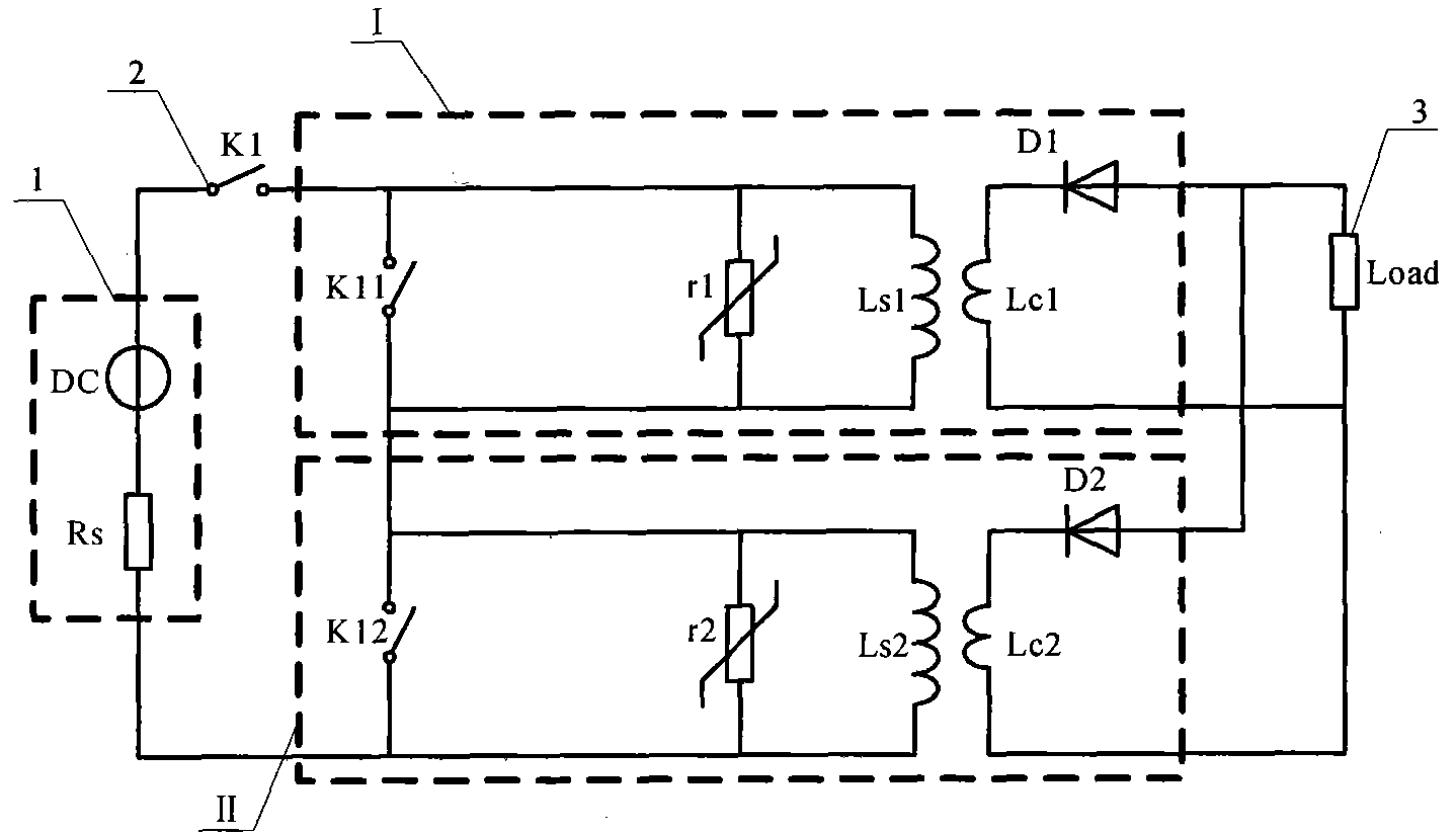
[0019] The module I circuit of the superconducting energy storage pulse power power supply (as shown in Figure 3) includes a charge and discharge switch K11, a non-linear discharge resistor r1, a pulse power tran...


PUM


Abstract

The invention discloses a superconducting energy storage impulse power electrical source, which comprises an initial charging electrical source, an electrical source switch, a follow current switch, a quench trigger device module of a superconducting energy storage electrical inducer and a load, wherein the quench trigger device module of the superconducting energy storage electrical inducer consists of a plurality of electrical source circuit modules which are connected with each other in parallel. Each electrical source circuit module has the following stricture that a charging-discharging switch and a nonlinear discharging resistor are arranged in a primary winding loop of a superconducting impulse power transformer in parallel, and a power diode is connected with the inner part of a secondary winding loop of the superconducting impulse power transformer. By adopting the structure, the superconducting energy storage impulse power electrical source can realize in-series charging andin-parallel charging of the plurality of modules, effectively realizes the impulse large current by amplifying and overlapping output impulse current with the superconducting impulse power transformer, and has the advantages of high energy-storing density and light weight and small volume of unit power electrical source.

Description

Technical field [0001] The invention belongs to the technical field of pulse power, and particularly relates to a pulse power source based on energy storage and discharge of a superconducting pulse power transformer. Background technique [0002] Pulsed power technology is an emerging discipline that has developed rapidly in recent decades. It refers to the technology that stores energy for a relatively long time, undergoes rapid compression and conversion, and then effectively releases it to the load. It is also called high power. Pulse technology. Early nuclear fusion research created an environment for it to grow, and the demand for basic defense research provided the impetus for its development. Generally speaking, pulse power devices include primary energy sources, intermediate energy storage and pulse shaping systems, conversion systems, and loads. The intermediate energy storage element is the basic element in the pulse power technology and the key component of the pulse...

Claims


Application Information

Patent Timeline
Patent Type & Authority Applications(China)
IPC IPC(8): H02M9/02
Inventor 李海涛董亮王豫邵慧陈天腾
Owner SOUTHWEST JIAOTONG UNIV
Why Eureka
Try Eureka