Duct single screw aircraft based on Magnus effect

An aircraft and propeller technology, applied in the field of aircraft, can solve problems such as control of difficult flight actions, complex structure of coaxial dual-propeller unmanned aircraft, and no flight attitude of propeller aircraft, so as to improve the influence of uncertain air turbulence, Simple structure and improved safety effect

Active Publication Date: 2013-03-27
HARBIN INST OF TECH
View PDF1 Cites 0 Cited by
  • Summary
  • Abstract
  • Description
  • Claims
  • Application Information

AI Technical Summary

Problems solved by technology

[0004] The purpose of the present invention is to provide a ducted single propeller aircraft based on the Magnus effect, to solve the problem that the Magnus effect force generated by the air flow is not proposed in the prior art to control the flight attitude of the propeller aircraft, resulting in coaxial The dual-propeller unmanned aerial vehicle has the problem of complex structure and difficult control of various flight actions

Method used


Image

  • Duct single screw aircraft based on Magnus effect
  • Duct single screw aircraft based on Magnus effect
  • Duct single screw aircraft based on Magnus effect

Examples


specific Embodiment approach 1

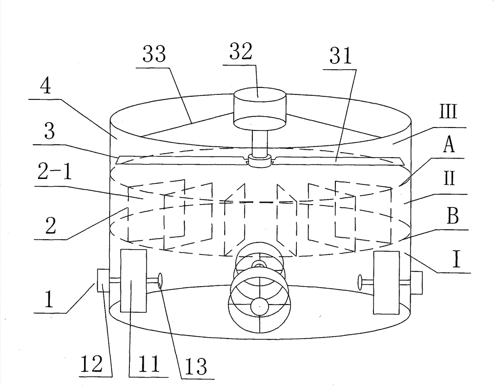
[0019] Specific implementation manner one: such as Figure 1~10 As shown, the ducted single-propeller aircraft based on the Magnus effect described in this embodiment includes a rudder device 1, an airflow adjustment device 2, a power device 3, and an aircraft housing 4; the aircraft housing 4 includes an outer circle The cylinder 41, the steering gear 1, the air flow adjusting device 2, and the power device 3 are arranged from bottom to top and mounted on the outer cylinder 41 in the axial direction (that is, the steering gear device 1, the air flow adjusting device 2 and the power device 3 The center lines of the three coincide with the axis of the outer cylinder 41);

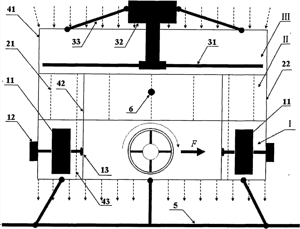
[0020] The steering gear device 1 is composed of four steering gear units, each steering gear unit includes a hollow wheel 11 and a motor 12; the four steering gear units are evenly arranged along the circumferential direction of the outer cylinder 41, and the four hollow The core wheel 11 is all placed in the i...

specific Embodiment approach 2

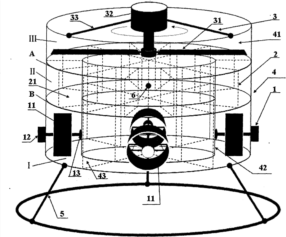
[0024] Specific implementation manner two: such as Figure 1~4 As shown, the power device 3 in this embodiment is composed of a propeller 31, a power source 32, and a frame 33. The power source 32 is fixed to the upper end of the outer cylinder 41 through the frame 33, and the propeller 31 is mounted on the drive of the power source 32. On the shaft, the drive shaft of the power source 32 drives the propeller 31 to rotate, and the axis of the drive shaft of the power source 32 coincides with the axis of the outer cylinder 41. The end position of the driving shaft (rotating shaft) of the power source 32 is directly above the total center of mass 6 of the aircraft to ensure the stability of the flight attitude. The propeller is fixed at the end of the rotating shaft. The other components and connection relationships are the same as in the first embodiment.

specific Embodiment approach 3

[0025] Specific implementation manner three: such as Figure 1~4 As shown, the aircraft housing 4 of this embodiment further includes an inner cylinder 42 which is coaxially arranged in the inner cavity of the outer cylinder 41, and the inner cylinder 42 is located below the power unit 3. The lower end surface of the inner cylinder 42 is flush with the lower end surface of the outer cylinder 41; the plurality of grid plates 21 are arranged in the annular area between the inner cylinder 42 and the outer cylinder 41. The provision of the inner cylinder 42 can further ensure that the spiral air flow is converted into a vertical jet air flow. Other components and connection relationships are the same as those in the first or second embodiment.


PUM


Abstract

The invention relates to a duct single screw aircraft based on Magnus effect, relating to a duct single screw aircraft. The invention solves the problems of poor safety, complex structure and difficult realization of various flying behaviour control of the traditional coaxial double-screw unmanned aircraft. The invention has the technical scheme that a steering engine duct (I), an airflow regulation duct (II) and a power duct (III) are sequentially communicated; a power device (3) is used for generating spiral airflows in the power duct (III); an airflow regulation device (2) is used for converting the spiral airflows in the power duct (III) into vertical jet-type airflows; and the vertical jet-type airflows regulated in the steering engine duct (I) generate Magnus effect force on the lateral surfaces of a hollow core wheel (11). In the invention, the Magnus effect force generated during the rotation of the hollow core wheel is used as control input, and the aircraft further realizes various flying behaviours. The invention has the advantages of simple and compact structure, low energy consumption, safety, flexible behaviour, and the like.

Description

Technical field [0001] The invention relates to a ducted single-propeller aircraft, in particular to a ducted single-propeller aircraft based on the Magnus effect, and belongs to the technical field of aircraft. Background technique [0002] At present, due to the use of two propellers in a coaxial dual-propeller UAV, under the same constraints, the propeller radius is only 70% of that of a single-rotor aircraft. Since the fuselage is included in the area of ​​the paddle disk, the overall longitudinal size is only about 60% of that of a single-propeller and tail-wing aircraft, thus reducing the moment of inertia of pitch and yaw. The above structural characteristics show that the heading control performance of coaxial dual-propeller aircraft is better than that of single-propeller aircraft with tail wing. But this is a design at the expense of two independent power units or a complex heading control system and a complex mechanical transmission system. At the same time, the high-...

Claims


Application Information

Patent Timeline
Patent Type & Authority Patents(China)
IPC IPC(8): B64C23/08B64C9/06
Inventor 赵杰金弘哲樊继壮王忠信
Owner HARBIN INST OF TECH
Why Eureka
Try Eureka