

Orthographic projection screen and manufacturing method thereof
A technology of forward projection screen and production method, which is applied in photography, photoengraving process of pattern surface, optics, etc., to achieve the effects of good color reproduction ability, high contrast and high gain
- Summary
- Abstract
- Description
- Claims
- Application Information
AI Technical Summary
Problems solved by technology
Method used
Image

Examples
Embodiment 1
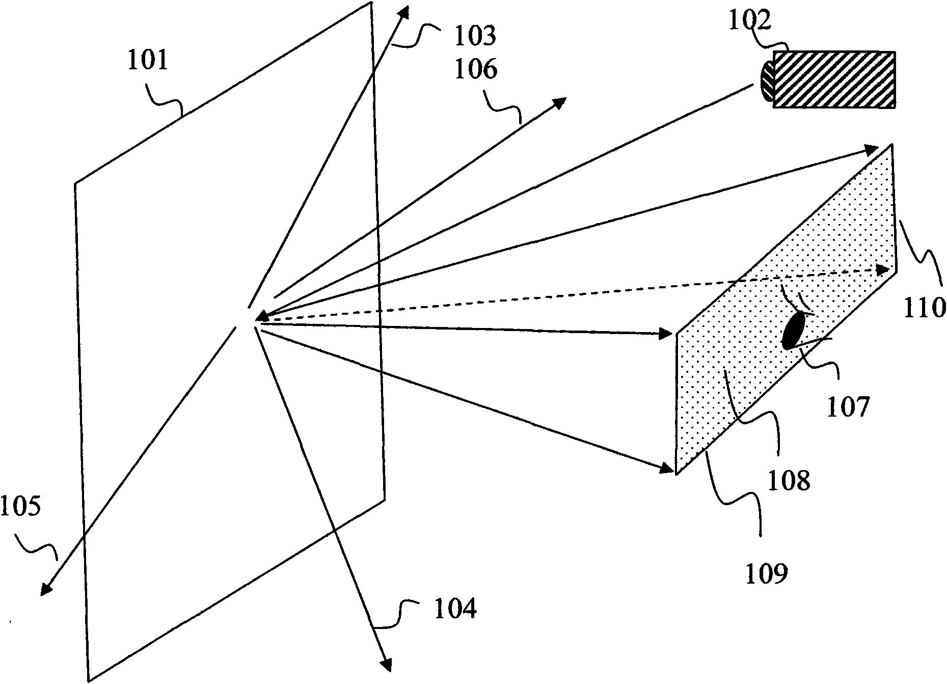
[0052] An example of the forward projection screen provided by the present invention is shown in Fig. 5, which is composed of an aspheric microlens array (501) and includes many concave microlens units. In one direction, the aspherical microlens array (502) has a larger optical power, which corresponds to a larger horizontal width of the observation zone ( figure 1 , 109); in the direction perpendicular to it, the microlens array (503) has a smaller optical power, corresponding to a larger horizontal width of the observation zone ( figure 1 , 110). Figure 5b It is a sectional view of an aspheric microlens array (501) in one direction, and has relatively large optical power. The microlenses (504) (505) (506) have different positions, and the inclinations of their optical axes are also different. Figure 5c is a cross-sectional view of an aspheric microlens array (501) in another vertical direction, and the focal power ratio is Figure 5b As shown, the microlenses (507), (50...
Embodiment 2
[0054] Another example of the forward projection screen provided by the present invention is shown in FIG. 9 , which is composed of an aspheric microlens array (901) and includes many convex microlens units. In one direction, the microlens array (902) has a larger optical power, which corresponds to a larger horizontal width of the observation zone ( figure 1 , 109); in the direction perpendicular to it, the microlens array (903) has a smaller optical power, corresponding to a smaller vertical width of the observation zone ( figure 1 , 110). Figure 9b It is a sectional view of an aspheric microlens array (901) in one direction, and has relatively large optical power. The positions of the lenses (904) (905) (906) are different, and the inclinations of their optical axes are also different. Figure 9cis a cross-sectional view of an aspheric microlens array (501) in another vertical direction, and the focal power ratio is Figure 9b As shown, the microlenses (907), (908) (909...
Embodiment 3
[0056] An example of the manufacturing method of the aspheric microlens array provided by the present invention is shown in FIG. 10 . A binary mask is used as the image source, and the binary mask can be obtained through a commercial mask making service organization. A binary mask of about 1 meter has been commercialized, making it possible to manufacture a large-area lens array. Specific steps are as follows:
[0057] 1. Coating a photosensitive material layer (1002) on the glass substrate (1001), such as the positive photoresist commonly used in large-scale integrated circuit technology, passing through the post-baking process (usually 80 ° C to 120 ° C, 1 to 2 hours ) to form a photoresist plate (1003).
[0058] 2. First exposure: use the first binary mask (1004) to stick to the photoresist plate, and use a uniform light source (1005) to expose the photoresist plate through the mask. During the exposure process, the binary mask The relative movement between the mold and t...
PUM
 Abstract
Description
Claims
Application Information