
Open magnetic circuit stacked coil component and process for producing the open magnetic circuit stacked coil component

A technology of stacking coils and open magnetic circuits, applied in coil manufacturing, inductance/transformer/magnet manufacturing, chemical instruments and methods, etc. , the temperature characteristics of the inductance value are flat, the temperature characteristics are flat, and the initial inductance is large.

Active Publication Date: 2012-11-07
MURATA MFG CO LTD
View PDF6 Cites 0 Cited by
  • Summary
  • Abstract
  • Description
  • Claims
  • Application Information

AI Technical Summary

Problems solved by technology

However, since the non-magnetic layer does not contain Ni, Ni tends to diffuse from the magnetic layer to the non-magnetic layer, and there is a problem that the temperature characteristic of the inductance of the laminated coil component deteriorates due to the diffusion of Ni (the temperature change rate of the inductance is large).
In particular, when the thickness of the non-magnetic layer is set relatively thin, there is a problem that the temperature characteristic of the inductance value is greatly deteriorated due to the diffusion of Ni from the magnetic layer to the non-magnetic layer.
In an open magnetic circuit type laminated coil component, in order to increase the initial inductance, it is preferable to make the thickness of the nonmagnetic layer as thin as possible. However, if the thickness of the nonmagnetic layer is 40 μm or less, the inductance value will actually increase. Deterioration of temperature characteristics

Method used


Image

  • Open magnetic circuit stacked coil component and process for producing the open magnetic circuit stacked coil component
  • Open magnetic circuit stacked coil component and process for producing the open magnetic circuit stacked coil component
  • Open magnetic circuit stacked coil component and process for producing the open magnetic circuit stacked coil component

Examples


Embodiment 1

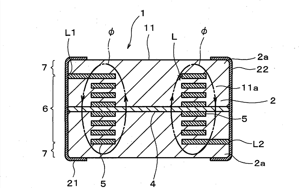
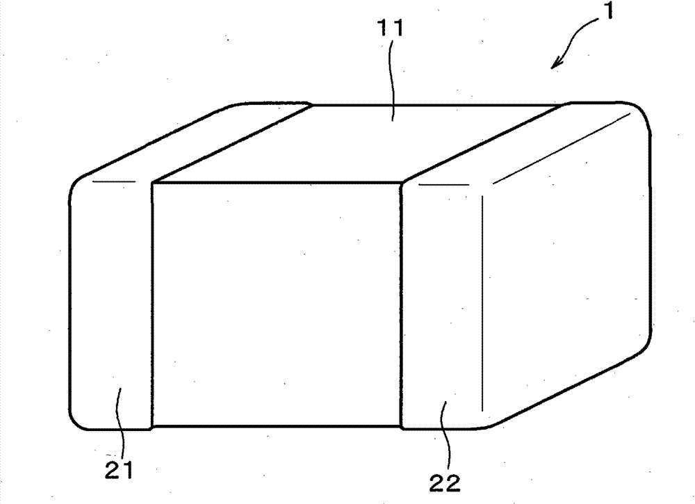
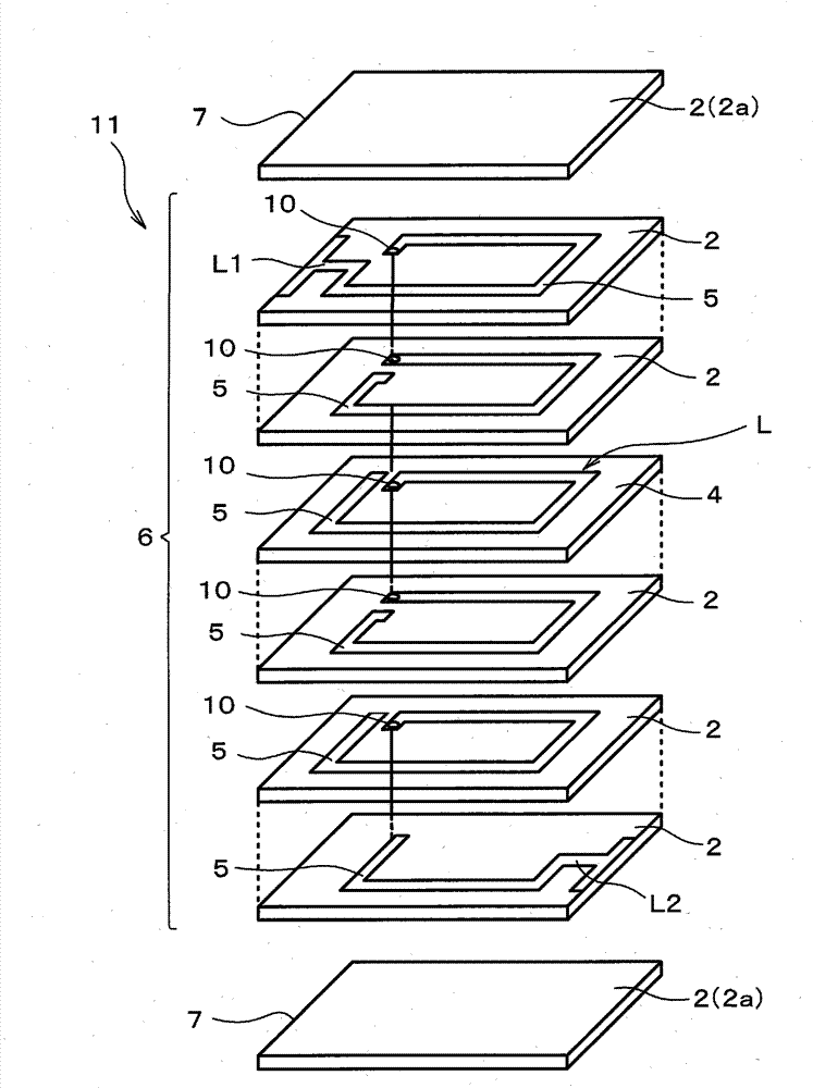
[0062] figure 1 is a cross-sectional view showing the structure of an open magnetic path type laminated coil component (a laminated inductor in the first embodiment) according to an embodiment (Embodiment 1) of the present invention, figure 2 is its stereogram, image 3 It is an exploded perspective view for explaining its internal structure and manufacturing method.

[0063] like Figure 1~3 As shown, the open magnetic circuit type laminated coil component 1 of this embodiment 1 is an open magnetic circuit type laminated inductor, and has a laminated body 11. The laminated body 11 is formed by laminating a plurality of coil conductors 5 and made of Ni-Zn- A plurality of magnetic layers 2 made of Cu-based ferrite material (refer to image 3 ) formed.

[0064] The laminated body 11 includes: a built-in coil laminated portion 6 in which a helical coil L is electrically connected to a plurality of coils arranged between a plurality of magnetic layers 2 through an interlayer ...

Embodiment 2

[0105] (Production of Magnetic Ceramic Green Sheets)

[0106] For 100 parts by weight of the magnetic material raw material (Ni-Zn-Cu-based ferrite material) having the same composition as in the case of Example 1 above, Co was mixed in the ratio shown in Table 2. 3 o 4 powder, and produced magnetic ceramic green sheets by the same method as in the case of Example 1 above. It should be noted that, in Table 2, the samples whose serial numbers are marked with * are outside the protection scope of the present application.

[0107] [Table 2]

[0108]

[0109] Thereafter, as in the case of Example 1, after via holes were formed at predetermined positions, predetermined conductor patterns for coils and via conductors for interlayer connection were formed on the surface of the magnetic ceramic green sheet.

[0110] It should be noted that, as the magnetic ceramic green sheet for the package portion, as in the case of the above-mentioned Example 1, the above-mentioned magnetic c...


PUM

PropertyMeasurementUnit
thicknessaaaaaaaaaa
thicknessaaaaaaaaaa
thicknessaaaaaaaaaa

Abstract

Disclosed is an open magnetic circuit stacked coil component that is less likely to cause defects between a nonmagnetic layer and a magnetic layer, causes no significant deterioration in temperature characteristics of inductance, even when the thickness of the nonmagnetic layer is reduced, and has excellent direct-current superimposition characteristics. An open magnetic circuit stacked coil component (1) comprises a laminate (11), formed of magnetic layers (2) stacked on top of each other, a coil (L) provided within the laminate (11), and a nonmagnetic layer (4) provided within the laminate (11) so as to cross a magnetic path formed by energization of the coil (L). The nonmagnetic layer is formed of a nonmagnetic material of a Zn-Cu-based ferrite. The magnetic layer is formed of a magnetic material. The magnetic material comprises 100 parts by weight of an Ni-Zn-Cu-based magnetic ferrite material and 0.1 to 2.0 parts by weight, in terms of Co3O4, of Co added to the Ni-Zn-Cu-based magnetic ferrite material. According to the above constitution, the difference in firing shrinkage between the magnetic layer and the nonmagnetic layer can be reduced to suppress the occurrence of cracksand the like, and, even when Ni is diffused from the magnetic layer to thenonmagnetic layer upon firing, the temperature characteristics of the inductance are rendered flat.

Description

technical field [0001] The present invention relates to a laminated coil component such as a laminated inductor, and more specifically, to an open magnetic path type laminated coil component having a structure in which a coil conductor is arranged inside a laminate formed by laminating magnetic layers and nonmagnetic layers and a method for manufacturing the same . Background technique [0002] In recent years, laminated coil components suitable for miniaturization are widely used. The laminated coil components are formed by laminating a plurality of coil conductor patterns and a plurality of magnetic layers, and have a structure in which a coil conductor is arranged in a laminated body. [0003] In such a laminated coil component, the inductance value of the closed magnetic circuit laminated coil component is approximately constant or gradually decreases until the superimposed DC current gradually increases to a certain current value, but after that, there is a possibility ...

Claims


Application Information

Patent Timeline
Patent Type & Authority Patents(China)
IPC IPC(8): H01F17/00H01F1/34H01F17/04H01F41/04
CPCC04B2235/3281C04B2237/582C04B2235/9615C04B2235/3284H01F41/0246C04B35/265C04B2235/3277H01F2017/0066C04B2235/6025H01F17/0013H01F41/046H01F1/344C04B2235/3279C04B2237/34H01F2017/002H01F27/255B32B18/00Y10T29/49073Y10T29/4902
Inventor 中村彰宏佐藤明子中辻阳一
Owner MURATA MFG CO LTD
Learn More