Rotation speed synchronizing signal-based spark plug sparking control device

A speed synchronization signal and control device technology, applied in the direction of automatic control, automatic control, electrical automatic control, etc., can solve problems such as adverse effects on engine performance, impact on spark plug service life, spark-over timing angle error, etc., and achieve great practical significance in production , Avoid invalid flashover, high ignition success rate

Inactive Publication Date: 2010-12-15
TIANJIN UNIVERSITY OF TECHNOLOGY
View PDF6 Cites 6 Cited by
  • Summary
  • Abstract
  • Description
  • Claims
  • Application Information

AI Technical Summary

Problems solved by technology

[0003] Most of the spark plug flashover control technologies and devices commonly used at present use a proximity switch (such as a Hall sensor) installed on the crankshaft of the engine. The proximity switch generates a trigger signal for each revolution when the machine rotates. The trigger signal collected twice calculates the engine speed and the spark plug flashover time required by the engine, and outputs the flashover control signal once per revolution. Since the engine needs to rotate two revolutions in each power cycle of the four-stroke machine, except for the compression stroke In addition to a flashover, the exhaust stroke of another circle will also produce a flashover, which is ineffective, not only wastes energy, but also affects the service life of the spark plug
[0004] In addition, this spark plug flashover control technology is based on the premise that the engine speed is constant, but the actual speed of the engine fluctuates between each power cycle and different corner positions in the same power cycle, which results in the use of two revolutions. There is a large angular error in the spark timing calculated by the generated trigger signal, and the performance of the engine is adversely affected

Method used


Image

  • Rotation speed synchronizing signal-based spark plug sparking control device
  • Rotation speed synchronizing signal-based spark plug sparking control device
  • Rotation speed synchronizing signal-based spark plug sparking control device

Examples


Embodiment Construction

[0026] In order to enable those skilled in the art to better understand the solution of the present invention, the present invention will be described below in conjunction with the accompanying drawings and embodiments.

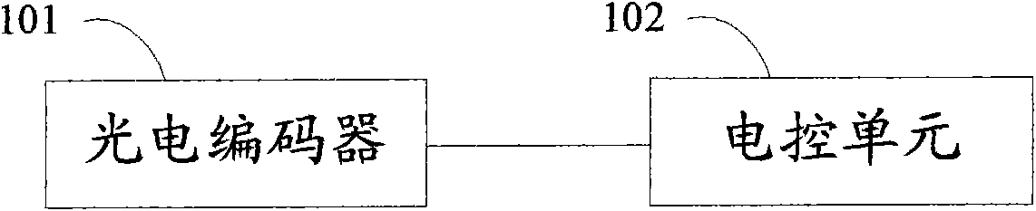
[0027] figure 1 An overall structural diagram of a spark plug flashover control device based on a rotational speed synchronization signal provided by the present invention.

[0028] see figure 1 , the present invention provides a spark plug flashover control device based on a speed synchronization signal, the device includes a photoelectric encoder 101 and an electronic control unit 102, wherein:

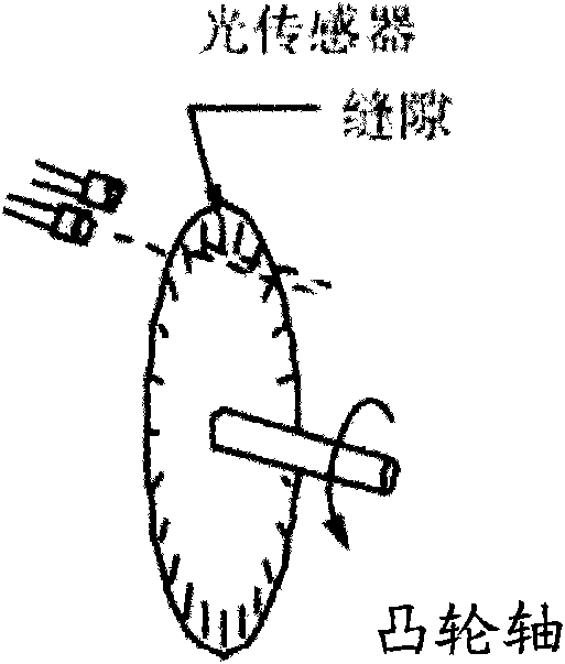
[0029] Photoelectric encoder 101, it is installed on the camshaft of engine, is used for the speed synchronous signal of real-time acquisition engine and top dead center signal and outputs to electric control unit 102 (being single-chip microcomputer);

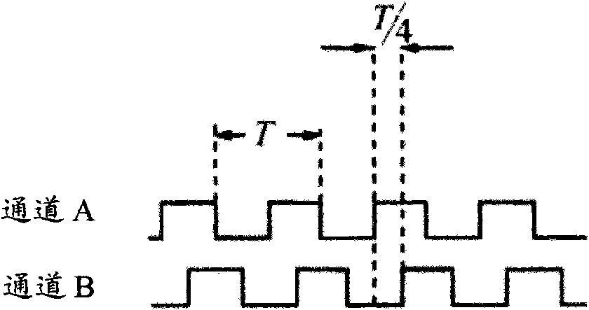
[0030] The electronic control unit 102 is connected with the photoelectric encoder 101, and is used to realize...


PUM


Abstract

The invention discloses a rotation speed synchronizing signal-based spark plug sparking control device. The device comprises a photoelectric encoder and an electric control unit, wherein the photoelectric encoder is arranged on a cam shaft of an engine for acquiring a rotation speed synchronizing signal and a top dead centre signal of the engine and outputting the signals to the electric control unit in real time; and the electric control unit is connected with the photoelectric encoder for counting interruption signals produced by overflowing by using a counter according to the received rotation speed synchronizing signal and top dead centre signal, so that preset periodic sparking of a spark plug of the engine is realized, and a multi-pulse sparking control signal is output to an ignition coil of the spark plug to control the spark plug to perform sparking for several times. The spark plug sparking control device of the invention can prevent ineffective sparking, realize the sparking close to the end point of a compression travel of a working cycle of the engine for several times and has the advantages of high sparking energy, high success rate of ignition and high timing accuracy of sparking, so the device is particularly suitable for spark ignition type natural gas engines requiring high ignition energy and is favorable for broad production and application.

Description

technical field [0001] The invention relates to the technical field of automatic control of internal combustion engines, in particular to a spark plug flashover control device based on a speed synchronization signal. Background technique [0002] At present, spark plug sparkover control technology and devices in spark ignition internal combustion engines are one of the main factors that determine the internal combustion quality, especially in engines that require high-energy ignition, the impact of spark plug flashover performance on the engine is more prominent. [0003] Most of the spark plug flashover control technologies and devices commonly used at present use a proximity switch (such as a Hall sensor) installed on the crankshaft of the engine. The proximity switch generates a trigger signal for each revolution when the machine rotates. The trigger signal collected twice calculates the engine speed and the spark plug flashover time required by the engine, and outputs th...

Claims


Application Information

Patent Timeline
Patent Type & Authority Applications(China)
IPC IPC(8): F02P5/15
Inventor 张德福沈国华
Owner TIANJIN UNIVERSITY OF TECHNOLOGY
Why Eureka
Try Eureka