Optical fiber loop for optical fiber gyroscope

An optical fiber loop and fiber optic gyroscope technology, which is used in Sagnac effect gyroscopes, gyroscopes/steering sensing equipment, optics, etc. The coil quality is difficult to achieve consistency and stability, affecting the mass production of fiber optic gyroscope products, etc., to achieve the effects of improving geometric control accuracy, performance indicators, winding efficiency, and control accuracy.

Active Publication Date: 2010-12-15
武汉长盈通光电技术股份有限公司
View PDF7 Cites 27 Cited by
  • Summary
  • Abstract
  • Description
  • Claims
  • Application Information

AI Technical Summary

Problems solved by technology

However, due to the limitation of the shape of the cylindrical optical fiber, there are many difficulties in the tension control, optical fiber misalignment, and length symmetry control of the optical fiber l...

Method used


Image

  • Optical fiber loop for optical fiber gyroscope
  • Optical fiber loop for optical fiber gyroscope
  • Optical fiber loop for optical fiber gyroscope

Examples


Embodiment 1

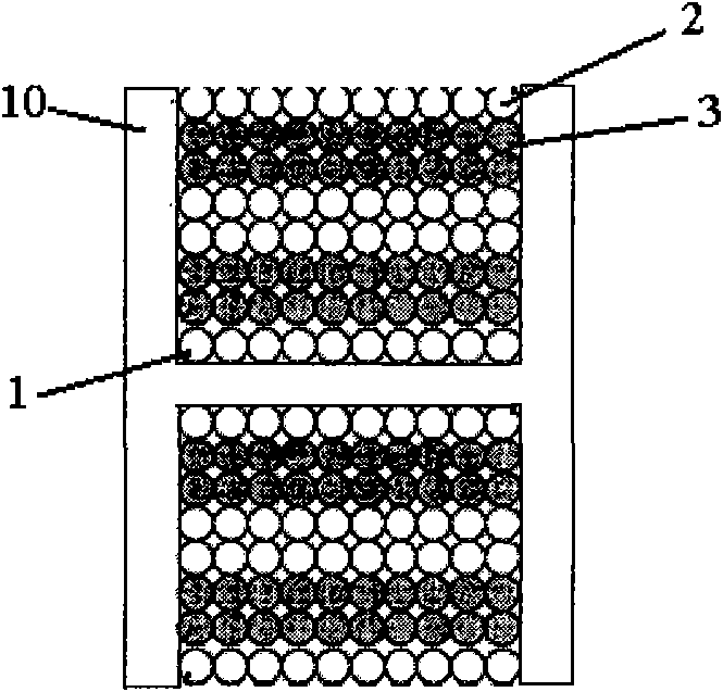
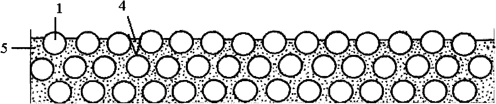
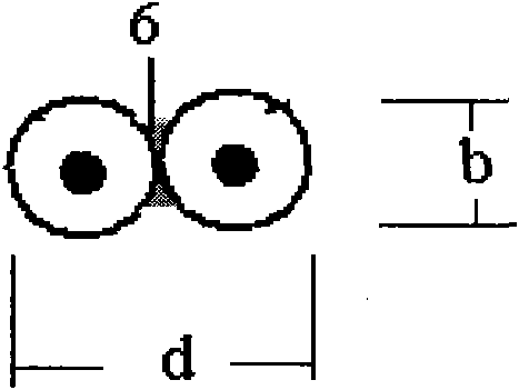
[0026] Two polarization-maintaining optical fibers 1 of the same type are bonded side by side with resin and cured by ultraviolet light to form a dual-core polarization-maintaining optical fiber ribbon 6. Half to another identical optical fiber reel, thereby obtaining the midpoint 9 of this one and band optical fiber ribbon, this midpoint is exactly the symmetrical midpoint needed when winding the ring, and the winding of the coil starts from this midpoint . Using the quadrupole winding method, starting from the symmetrical midpoint, the optical fiber ribbons on the two fiber distribution discs are wound onto the sensing skeleton 10 in sequence, Figure 4 and Figure 5 The key steps of the quadrupole winding method are given. The dual-core polarization-maintaining optical fiber ribbon 6 is equally divided into left and right sections and wound on the left and right fiber splitters 7 and 8, and the midpoint of the optical fiber ribbon is 9 in the figure. Then the reel-shaped...

Embodiment 2-8

[0029] In Embodiment 2-8, the same parallel structure design is adopted, and the quadrupole symmetrical winding method is also used to wind the optical fiber ring, and the parameters of the parallel tape, the parameters of the ring skeleton and the parameters of the optical fiber ring after winding are See Table 1 for polarization crosstalk parameters. Wherein the full text measurement condition is identical with embodiment 1.

[0030] Table 1: Parallel parameters, ring bobbin parameters, and polarization crosstalk parameters of the fiber ring after winding

[0031]

[0032] It can be seen from Table 1 that, using the polarization-maintaining optical fiber ribbon of the present invention to wind the optical fiber ring, the crosstalk at room temperature remains quite stable, and at the same time, the crosstalk at full temperature varies around 3dB, and the distribution is concentrated. It shows that the optical fiber loops wound by the polarization-maintaining optical fiber...


PUM

PropertyMeasurementUnit
Depthaaaaaaaaaa

Abstract

The invention relates to an optical fiber loop for an optical fiber gyroscope. The loop comprises a sensing framework and a polarization maintaining fiber wound on the sensing framework and is characterized in that: the polarization maintaining fiber is a polarization maintaining fiber ribbon which is formed by bonding 2*n polarization maintaining fibers in parallel, wherein n is 1, 2, 3 and the like and the polarization maintaining fiber ribbon with 2*n cores is formed; the head and the tail of adjacent optical fibers at two head ends of the wound polarization maintaining fiber ribbon are connected with each other by melting; and the head end of a first optical fiber and the tail end of a last optical fiber are taken as an input end and an output end of the optical fiber loop. The loop has the advantages of greatly improving the winding quality and increasing the winding speed of the optical fiber loop, improving the performance index and winding efficiency of the optical fiber loop, improving the geometry control accuracy and temperature performance of a circling optical fiber, improving the temperature stability and accuracy index of the optical fiber loop, simplifying the winding process of the optical fiber loop, and high repeatability and improving winding efficiency, along with simple and reliable winding mode.

Description

technical field [0001] The invention relates to an optical fiber loop used for an optical fiber gyroscope, and belongs to the technical field of optical fiber gyroscopes. Background technique [0002] The fiber optic gyroscope was born in 1976. It is a new type of sensor that uses fiber optic sensing technology to measure the space inertial rotation rate. It has developed into a new mainstream instrument with epoch-making characteristics in the field of inertial technology. Compared with the laser gyroscope, it has a wider application range, low cost, small size and light weight. The application prospect of fiber optic gyroscope is very broad. It is not only used in the navigation of aircraft and ships, missile guidance, and high-precision attitude control of spacecraft, but also can be used in the guidance of high-end cars for civilian use, as well as robots and automatic control systems, etc. . [0003] The fiber optic loop is the sensing element of the fiber optic gyros...

Claims


Application Information

Patent Timeline
IPC IPC(8): G01C19/72
CPCG02B6/4457G01C19/722
Inventor 皮亚斌
Owner 武汉长盈通光电技术股份有限公司
Why Eureka
Try Eureka