
Cut-off frequency self-tuning method and circuit for filter

A technology of cut-off frequency and filter, applied in the direction of automatic power control, frequency selection, two-terminal pair network, electrical components, etc., can solve the problem of filter cut-off frequency sensitivity, etc.

Inactive Publication Date: 2010-12-15
FUDAN UNIV
View PDF2 Cites 4 Cited by
  • Summary
  • Abstract
  • Description
  • Claims
  • Application Information

AI Technical Summary

Problems solved by technology

The cutoff frequency of the filter is extremely sensitive to the process angle, and there will be a deviation of up to 30% at each process angle

Method used


Image

  • Cut-off frequency self-tuning method and circuit for filter
  • Cut-off frequency self-tuning method and circuit for filter
  • Cut-off frequency self-tuning method and circuit for filter

Examples


Embodiment Construction

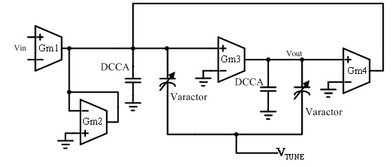
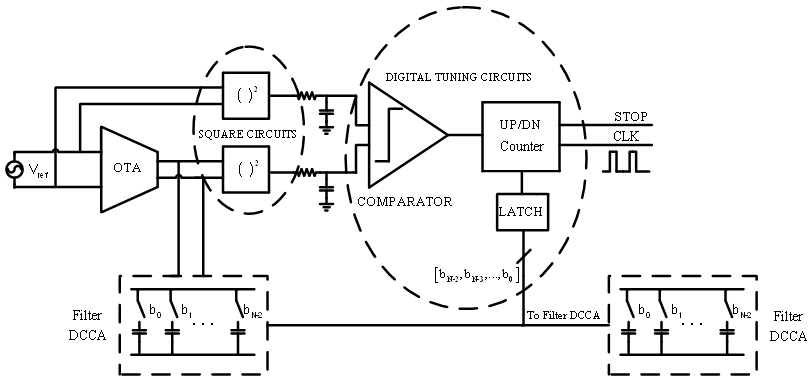
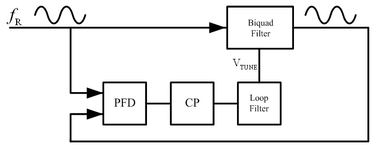
[0017] The present invention will be described in detail below in conjunction with the circuit diagram. figure 1 It is a diagram of the Biquad structure in the filter, in which the load capacitance is connected in parallel by a 5bit DCCA and a variable capacitor, and the capacitance of the variable capacitor under normal conditions is equal to the minimum bit capacitance of DCCA. Gm1, Gm2, Gm3, and Gm4 are transconductance amplifiers that constitute a biquadratic structure. When V TUNE When changing from 0V to 1.2V, the variation range of the variable capacitance is slightly larger than the minimum bit capacitance value of DCCA. Coarse tuning begins by setting V TUNE The voltage is biased to 0.6V. then start figure 2 The digitally tuned loop (MLL amplitude-locked loop) is shown. Among them, the square circuit detects the amplitude of the reference signal and the output signal of the integrator, and then outputs 1 or 0 through the comparator to control the counting direct...


PUM


Abstract

The invention belongs to the technical field of integrated circuit design and discloses a frequency self-tuning method and a frequency self-tuning circuit for a filter. The self-tuning circuit comprises a magnitude-locked loop (MLL) and a phase-locked loop (PLL). The self-tuning method and the self-tuning circuit correct the cut-off frequency of the filter by a coarse and fine tuning combined process. The self-tuning method comprises the following steps of: firstly, adopting the MLL to coarsely tune the cut-off frequency of the filter by regulating a control bit of a digital control capacitor array, wherein an error is a least significant bit (LSB) of the digital control capacitor array at the moment; secondly, regulating a capacitance value of a varactor by using the PLL and by VTUNE generated by a phase identifier and a charge pump; and finally, precisely matching the cut-off frequency of the filter with a reference frequency. The method has a wide tuning range and high tuning precision, only regulates capacitance and has no influences on the performance of the filter and therefore has a great practical value.

Description

technical field [0001] The invention belongs to the technical field of wireless communication, and in particular relates to a filter frequency self-tuning method and circuit. Background technique [0002] With the development of wireless communication, more and more communication standards have sprung up, and the development trend of miniaturization and miniaturization of electronic equipment requires the integration of more functions in a small area. Therefore, it has become a development trend to be compatible with multiple modes at the same time. The analog filter is a very important module of the analog baseband processing part of the radio frequency wireless communication chip and the signal processing chip. The change of the cutoff frequency of the filter and the suppression of the out-of-band signal determine whether the entire transceiver is compatible with multiple modes. Communication standards, and the accuracy of the cutoff frequency has a decisive effect on the...

Claims


Application Information

Patent Timeline
IPC IPC(8): H03H11/04H03L7/08
Inventor 李巍高亭樊锦涵李宁任俊彦
Owner FUDAN UNIV
Learn More