

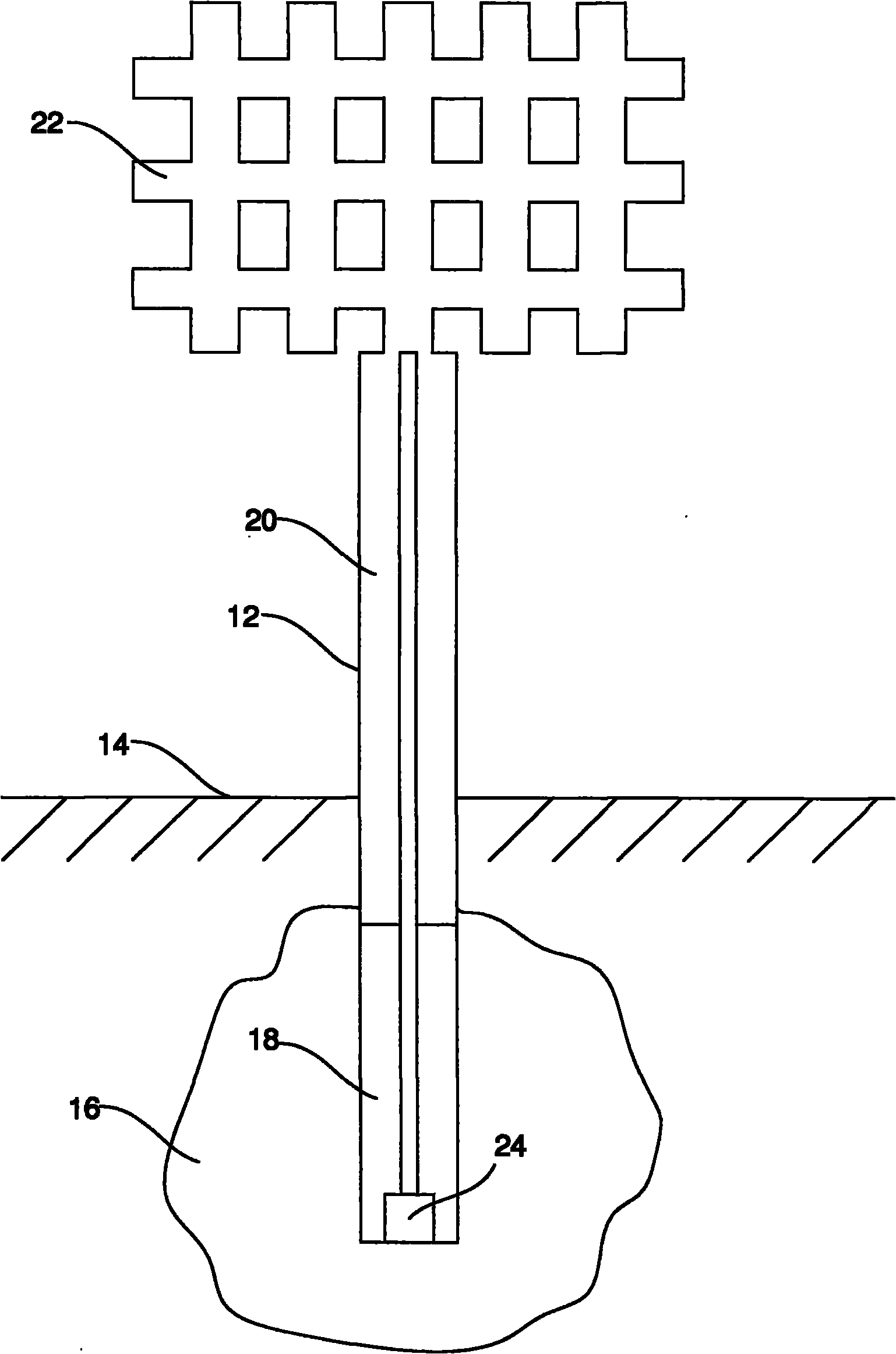
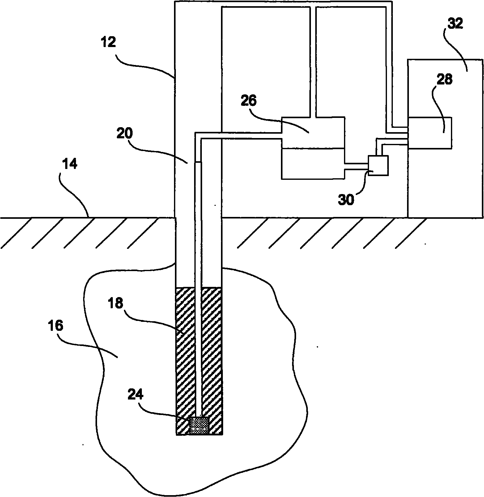
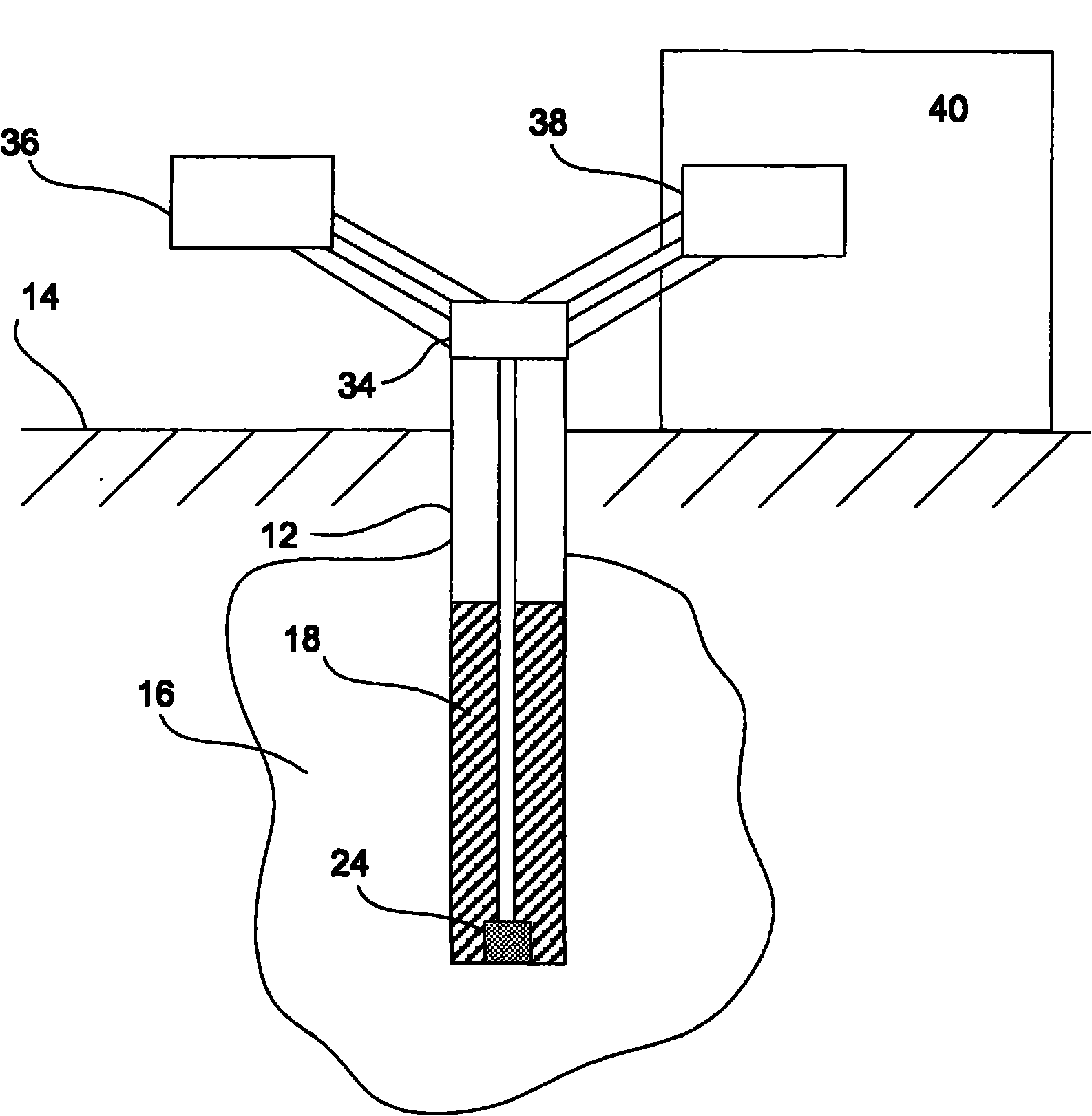
Ground-coupled heat exchange for heating and air conditioning applications
A heat exchanger and thermal energy technology, which is applied in the field of ground coupling/soil source/ground source thermosiphon, and the field of ground coupling thermosiphon heating and cooling structures, which can solve the problems of thermal short circuit and efficiency drop, non-optimal heat transfer coupling, etc.
- Summary
- Abstract
- Description
- Claims
- Application Information
AI Technical Summary
Problems solved by technology
Method used
Image

Examples
example 1
[0057] Example 1 - Heat load calculations for typical residential buildings in Utah
[0058] Solar energy available in Utah is about 1670 kWh / m 2 / year. At 70% solar collection efficiency, this solar energy will be about 1169 kWh / m 2 / year or 4.2GJ (gigajoules) / m 2 / year. Use solar constant 1.370kW / m 2 , 4.6 kWh / m 2 / day annual average, 1.7 kWh / m 2 / day monthly average (minimum in December) and 7.4 kWh / m 2 Solar energy is calculated as the monthly average (maximum in June) per day.
[0059] The table below represents heating and cooling loads based on data from Salt Lake City, Utah.
[0060] Table 1
[0061]
[0062]
[0063] Table 2
[0064]
[0065] From Table 1 and Table 2, the annual heating energy used for residential buildings is about: Q 加热 =29GJ, the annual cooling energy used for residential buildings is about: Q 冷却 = 82GJ.
example 2
[0066] Example 2 : Thermal energy storage scale of a family house (One Family House) (simplified calculation)
[0067] Can bear a typical family living room (150m 2 × 2 floors + basement) of the annual energy load of the soil cylinder (soil cylinder) size to calculate the energy recovery efficiency for underground thermal energy storage. This calculation uses the energy calculations from Example 1 (Q 冷却 =82×10 9 J, Q 加热 =29×10 9 J), and assuming the following properties of the soil column: η E =0.60, ΔT=15℃, H=10m, ρc P ≈2×10 6 J / m 3℃ (wet soil). Use the following equation:
[0068]
[0069] The resulting estimate R 冷却 is about 9.3m while R 加热 It is about 7.2m. This calculation demonstrates the feasibility of the structures described herein. Of course, the final scale will depend on the specific soil, environment and heating / cooling needs required.
example 3
[0071] As an example, the following 2D model was used to evaluate the performance of a set of 7 thermosiphons for frozen soil and the application of frozen soil as heat sink for air conditioning. Preliminary models of frozen and thawed water-soaked soils were created using the commercially available software package COMSOL Multiphysics 3.3. The geometric model chosen for the analysis was an array of six thermosyphons placed at the corners of a symmetrical hexagon with a seventh thermosyphon placed at the center of the hexagon. Taking advantage of the symmetry of the system, a quarter circle with a radius of 5 m was selected as the domain of interest. Three thermosyphons are modeled in this domain: one is positioned centrally, while the other two are arranged 60 degrees apart from one of them on the axis of symmetry. The distance between the thermosiphons is 1.5 meters. Only thermal conduction is modeled in this basic rendition.
[0072] Use the ambient temperature model for...
PUM
 Abstract
Description
Claims
Application Information