Permanent magnetic synchronous motor in wide weak-magnetic speed-regulating range
A permanent magnet synchronous motor, field weakening speed regulation technology, applied in synchronous motors with static armatures and rotating magnets, synchronous machine parts, magnetic circuit rotating parts and other directions, can solve problems such as increasing inverter capacity , to achieve the effect of improving the speed regulation range, high structural strength and good application prospects
- Summary
- Abstract
- Description
- Claims
- Application Information
AI Technical Summary
Problems solved by technology
Method used
Image


Examples
specific Embodiment approach 1
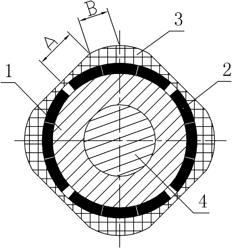
[0062] Specific implementation mode one: the following combination Figure 9 to Figure 16 Describe this embodiment. The permanent magnet synchronous motor with wide field-weakening speed regulation range in this embodiment includes a stator and a rotor. There is an air gap between the stator and the rotor. The stator is composed of a stator core and a stator winding. The stator winding adopts double-layer short The distance winding is characterized in that the rotor includes a rotor yoke 1, a plurality of permanent magnets 2, a magnetic rotor sheath 3 and a rotor shaft 4, and the magnetic rotor sheath 3 is made of silicon steel sheet, magnetic alloy steel or SMC material.
[0063] The outer surface of the rotor shaft 4 is provided with a rotor yoke 1, and a plurality of permanent magnets 2 are arranged between the outer surface of the rotor yoke 1 and the inner surface of the magnetic rotor sheath 3,
[0064] The number of motor pole pairs is p, and each rotor pole is composed...
specific Embodiment approach 2
[0078] Specific implementation mode two: the following combination Figure 13 with Figure 14 This embodiment is described. The difference between this embodiment and Embodiment 1 is that it also includes a narrow magnetic bridge 5, and a narrow magnetic bridge 5 is provided at the gap between two adjacent rotor poles. The narrow magnetic bridge 5 will The rotor yoke 1 and the magnetic rotor sheath 3 are fixedly connected together, and other structures and connection methods are the same as those in the first embodiment.
[0079] The magnetic rotor sheath 3 adopts an integrated structure with the rotor yoke 1, and the two are connected together by a narrow magnetic bridge 5, which can improve the structural strength of the rotor.
[0080] When the diameter of the rotor of the motor is small, the rotor yoke 1 can be eliminated, and the permanent magnet 2 can be directly pasted on the outer surface of the rotor shaft 4 made of magnetically permeable material, such as Figure 1...
specific Embodiment approach 3
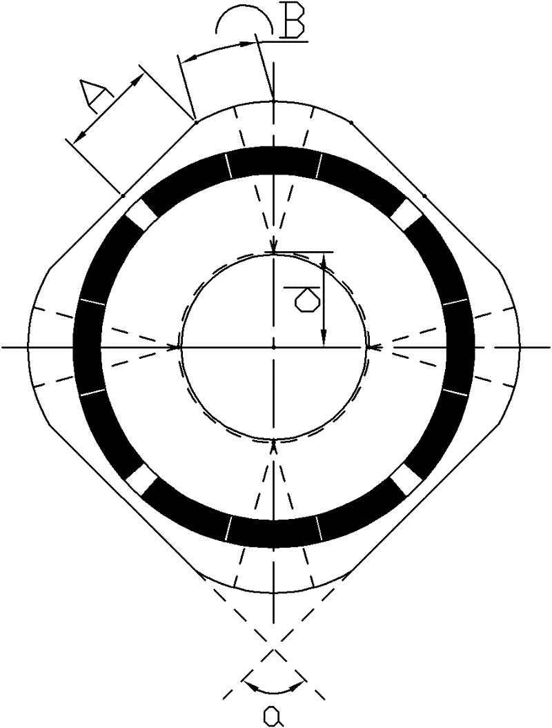
[0081] Specific implementation mode three: the following combination Figure 15 with Figure 16 Describe this embodiment, the difference between this embodiment and Embodiment 1 is that it also includes a rotor magnetic bridge 6, and 2n-1 permanent magnets 2 in each rotor pole are fixedly connected together with the rotor magnetic bridge 6, Other structures and connection modes are the same as those in the first embodiment.
[0082] There is a rotor magnetic bridge 6 between the permanent magnets 2 in each rotor pole, which can not only improve the structural strength of the rotor, but also increase the direct axis inductance and expand the constant power speed regulation range of the motor.
[0083] When the diameter of the rotor of the motor is small, the rotor yoke 1 can be eliminated, and the permanent magnet 2 can be directly pasted on the outer surface of the rotor shaft 4 made of magnetically permeable material, such as Figure 16 shown.
PUM
 Abstract
Description
Claims
Application Information
 - R&D
- Intellectual Property
- Life Sciences
- Materials
- Tech Scout
- Unparalleled Data Quality
- Higher Quality Content
- 60% Fewer Hallucinations
Browse by: Latest US Patents, China's latest patents, Technical Efficacy Thesaurus, Application Domain, Technology Topic, Popular Technical Reports.
© 2025 PatSnap. All rights reserved.Legal|Privacy policy|Modern Slavery Act Transparency Statement|Sitemap|About US| Contact US: help@patsnap.com