Multilayer gas distribution full circulation carbonization furnace

A full cycle, dry distillation furnace technology, applied in the field of coal chemical industry, can solve the problems of lower thermal efficiency and oil recovery rate, lower oil recovery efficiency, and difficulty in uniform heating, etc., to achieve significant dry distillation effect, increase oil recovery rate, and complete dry distillation effect

Active Publication Date: 2010-12-29
中国寰球工程有限公司辽宁分公司 +1
View PDF2 Cites 20 Cited by
  • Summary
  • Abstract
  • Description
  • Claims
  • Application Information

AI Technical Summary

Problems solved by technology

Since the furnace relies on the high-temperature circulating gas input from the gas inlet at the waist and the gas from the generating section to provide heat for the retort section, the heating method is a single-layer gas distribution, which makes it difficult to provide uniform heating, which directly affects the retort effect, reduces thermal efficiency and oil recovery Rate
The oil recovery rate is only about 65%, resulting in a waste of resources; secondly, when the gas in the generation section supplies heat for the retort section, because the gas contains excess oxygen, it is very easy to cause oil burning in the retort section, which not only reduces the oil recovery efficiency, but also causes local high temperature. "Smelting Furnace" Happened

Method used


Image

  • Multilayer gas distribution full circulation carbonization furnace
  • Multilayer gas distribution full circulation carbonization furnace

Examples


Embodiment Construction

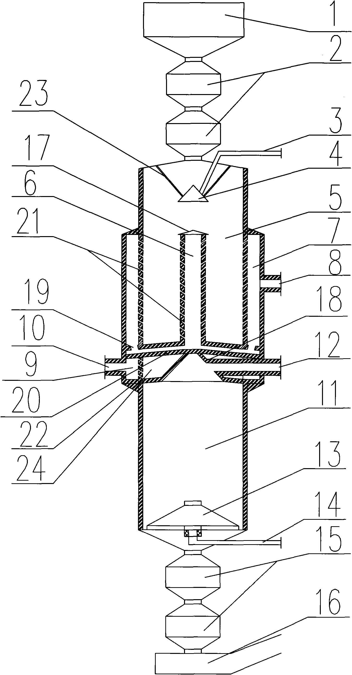
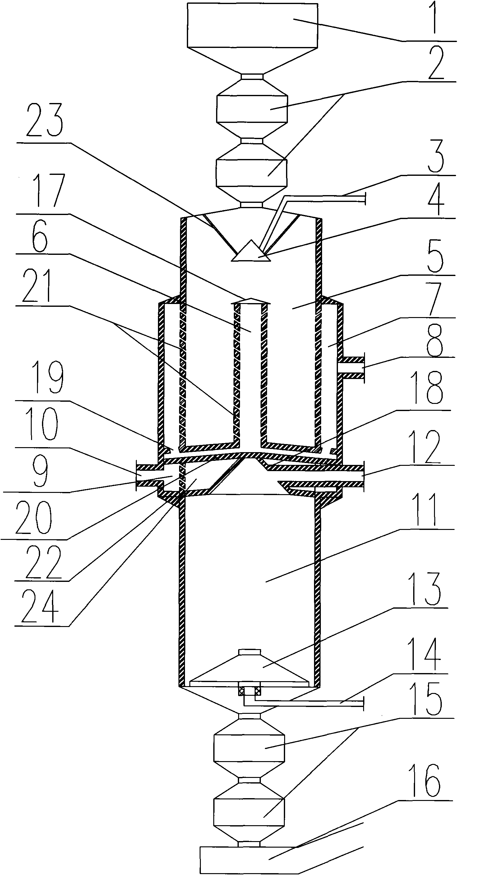
[0009] As shown in the figure, the present invention is composed of a furnace body and a discharge system and a slagging system at the top and bottom of the furnace body; the discharge system at the top of the furnace body includes a storage bin 1 and a lower hopper 2, and the lower hopper 2 is composed of The upper and lower valves are separated. The slagging system at the bottom of the furnace body includes an ash discharge hopper 15 and ash water cooling tank 16, and the ash discharge hopper 15 is two upper and lower ones separated by a valve. The above-mentioned double lower hopper 2 is used for feeding, and the double-row ash hopper 15 is used for ash discharge, which ensures that the gas in the retort furnace does not leak when discharging or slagging, and improves the capacity of a single furnace; the furnace body is divided into each other by the arch legs 20 in the middle. Connected dry distillation section 5 and generation section 11. The arched leg 20 is a hollow c...


PUM


Abstract

The invention discloses a multilayer gas distribution full circulation carbonization furnace which comprises a furnace body, a discharge system and a slag discharge system, wherein the discharge system is arranged on the top of the furnace body, the slag discharge system is arranged at the bottom of the furnace body, the furnace body is divided into a carbonization section at the upper part and ageneration section at the lower part by an arched leg arranged at the middle part of the furnace body, a carbonization product outlet is arranged at the upper part of the carbonization section, an air supply system is arranged at the lower part of the generation section, a gas seal section which is communicated with a gas-seal gas inlet is arranged between the carbonization section and the generation section, and an annular gas distribution chamber which is communicated with an inner cavity of the carbonization section through a gas distribution hole and also communicated with a circulation gas inlet is arranged outside the carbonization section, a center gas collection cavity is arranged in the carbonization section, the upper end of the center gas collection cavity is closed, the lower end of the center gas collection cavity is communicated with the circulation gas inlet, a gas distribution hole is arranged at the middle part of the center gas collection cavity, and a generation gasoutlet is arranged at the upper part of the generation section. The invention has the advantages of small heat carrier jet radius, more uniform gas distribution and heating, high heating and oil production efficiency, and the like, can fundamentally avoid the oil firing phenomenon, makes up a blank of the kind of carbonization furnaces and is worthy of popularization and application.

Description

1. Technical field [0001] The invention belongs to the technical field of coal chemical industry, and in particular relates to a multi-layer gas distribution full-cycle retort furnace. 2. Background technology [0002] As the world's energy consumption continues to grow, non-renewable energy sources such as coal, oil, and natural gas are increasingly scarce, and shale oil as a supplement to energy has attracted more and more attention. In the middle and late 20th century, many countries such as the United States, Estonia, and Brazil They are actively researching and developing new technologies for oil shale carbonization and designing new carbonization furnaces. my country's shale oil industry also began to develop in the late 20th century and has a history of several decades. At present, the most used internal heat retort furnace is composed of a feeding system, a furnace body and a slag discharge system. The furnace body is divided into an upper retort section and a lowe...

Claims


Application Information

Patent Timeline
Patent Type & Authority Applications(China)
IPC IPC(8): C10B53/06C10B31/02C10B41/00C10B49/02
Inventor 李柏张晶魏永巨都浩陈维思吴勃王淳邹靖涵
Owner 中国寰球工程有限公司辽宁分公司
Why Eureka
Try Eureka