Manufacturing method of stacked electrodes by winding type electrode stacking and stacked electrode thereby

A technology of electrode stacks and electrodes, applied in the direction of final product manufacturing, sustainable manufacturing/processing, circuits, etc., can solve problems such as battery life reduction

Inactive Publication Date: 2010-12-29
ENERTECH INT
View PDF3 Cites 10 Cited by
  • Summary
  • Abstract
  • Description
  • Claims
  • Application Information

AI Technical Summary

Problems solved by technology

The problem with this approach as shown in Figure 2B is that the lifespan of the battery decreases during long-term charging and discharging due to the difference in the concentrated stress on the central and edge parts of the wound unit

Method used


Image

  • Manufacturing method of stacked electrodes by winding type electrode stacking and stacked electrode thereby
  • Manufacturing method of stacked electrodes by winding type electrode stacking and stacked electrode thereby
  • Manufacturing method of stacked electrodes by winding type electrode stacking and stacked electrode thereby

Examples


Embodiment 1

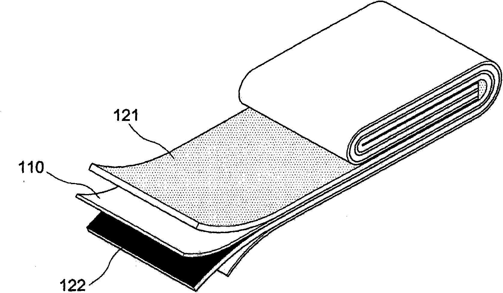
[0042] The anode electrode (i.e., the first electrode 121) is made by mixing lithium nickel cobalt manganese (LiNi x co y mn z o 2 ) (i.e. anode active material), carbon black (i.e. conductive material) and polyvinylidene fluoride PVDF (i.e. binding substance) and NMP (N-methylpyrrolidone) solvent to obtain a slurry, in the aluminum charge collector The slurry is coated on top and finally dried. The cathode electrode (i.e. the second electrode 122) was made by obtaining a slurry of the same composition as in the anode electrode composition except that graphite was used instead of lithium transition metal oxide, coated on a copper charge collector The slurry is finally dried to finish.

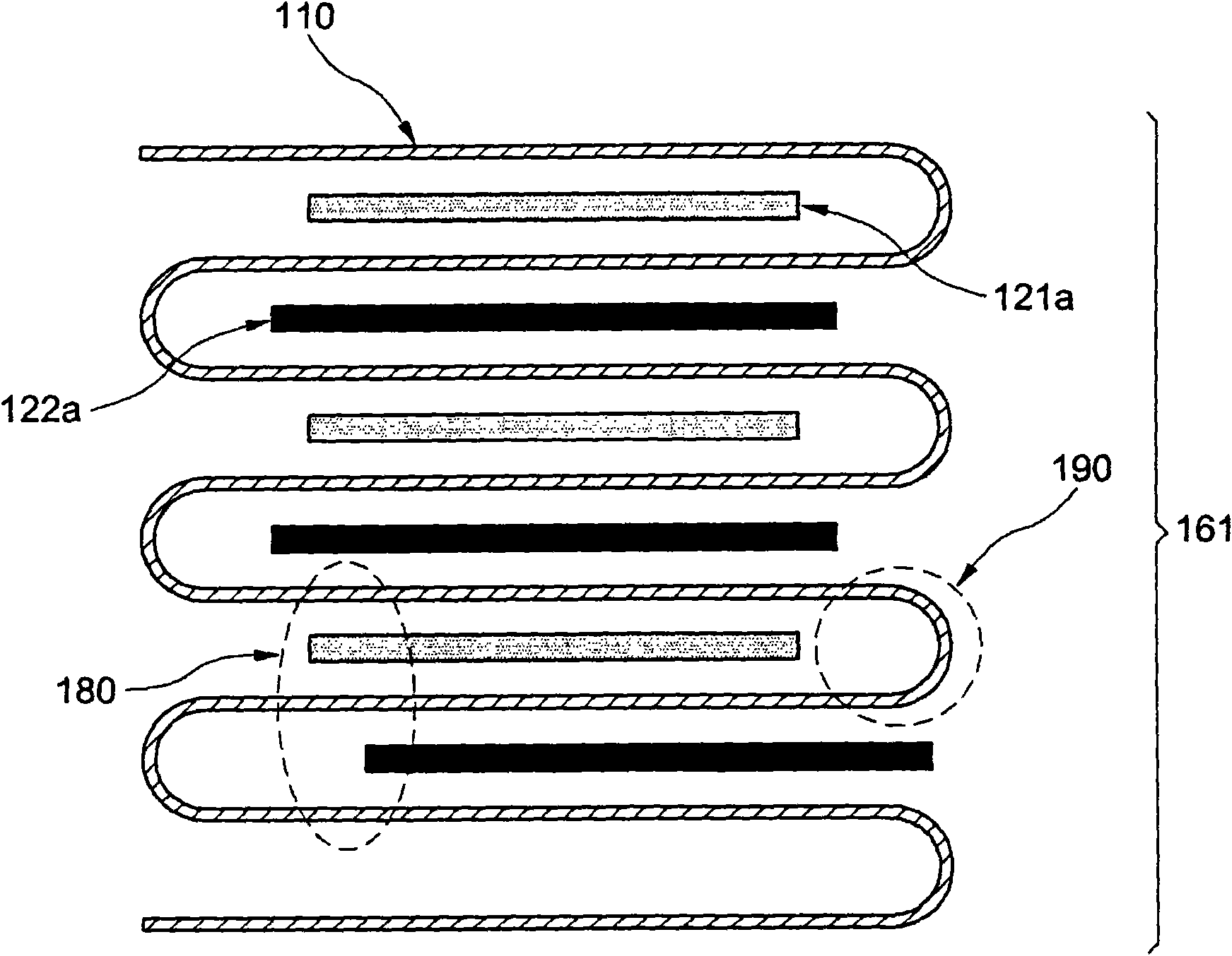
[0043] Each anode electrode and cathode electrode is stamped according to the design size, but the size design of the cathode electrode is larger than the size of the anode electrode. A porous film made of polyethylene material is used as the isolation layer 110 . The separation layer 110...

Embodiment 2

[0046] An electrode stack and a rechargeable battery using the electrode stack were fabricated in the same manner as in Example 1 above, except that the same anode and cathode electrodes as in Example 1 were used, but both ends of the separator were separated from two Release layer rolls 171 and 172 are withdrawn and joined together.

Embodiment 3

[0048] An electrode stack and a rechargeable battery using the electrode stack were manufactured in the same manner as in Example 1 above, except that the same electrode stack as in Example 1 was used, but in the process of forming the unit electrode main body, initially Stacked anode electrodes are coated and dried on only one side, as in Figure 5 shown. as from Figure 5 The innermost electrodes of the electrode assembly shown, each have only one side coated with slurry on the partial electrode 125 and 126 for the anode charge collector, but the other side of the partial electrode 125 and 126 is not coated with slurry and arranged opposite each other.


PUM


Abstract

The present invention relates to a electrode stacking method, wherein electrodes are stacked in such a manner that the electrodes are disposed to face each other on both sides of a separation layer to which predetermined tension force is applied along the longitudinal direction of said separation layer, and the electrode assembly is turned so that another separation layer is formed outside the electrodes. According to the rechargeable lithium ion batteries in accordance with the present invention, the electrode stack in which the arrangement of anode electrodes and cathode electrodes is not disordered because uniform stress is applied to the entire battery and the separation layer maintains a constant tension force can be fabricated. Accordingly, the lifespan of a rechargeable lithium ion battery can be increased, and the input and output characteristic of the battery can be improved.

Description

technical field [0001] The present invention relates to a method of manufacturing a rechargeable lithium-ion battery stack and an electrode stack manufactured by the method. Specifically, the present invention relates to a winding type electrode stacking method in which the electrodes are stacked in such a manner that the electrodes are placed to face each other on both sides of a separation layer with a predetermined tension along the separation layer The longitudinal direction of is applied to the separator and the electrode assembly is turned so that another separator is formed outside the electrodes. The invention also relates to an electrode stack for a rechargeable lithium ion battery fabricated by this method. Background technique [0002] With the development of the information communication industry, the use of portable devices continues to increase, and the demand for rechargeable lithium ion batteries with large capacity, high performance, and long life to meet th...

Claims


Application Information

Patent Timeline
Patent Type & Authority Applications(China)
IPC IPC(8): H01M10/38H01M10/36H01M10/0525H01M10/0583
CPCH01M10/0583Y02E60/122H01M10/0525Y10T29/49108Y02E60/10Y02P70/50H01M10/0587H01M50/46
Inventor 金荣在李汉城金奎植禹锺万
Owner ENERTECH INT
Why Eureka
Try Eureka