Wheel of motor vehicle generating power in motion
A technology of motor vehicles and linear generators, which is applied in the field of mechanical hydraulic power generation devices, automobile wheels, and motor wheels, and can solve problems such as poor mileage performance and insufficient power
- Summary
- Abstract
- Description
- Claims
- Application Information
AI Technical Summary
Problems solved by technology
Method used
Image
Examples
Embodiment 1
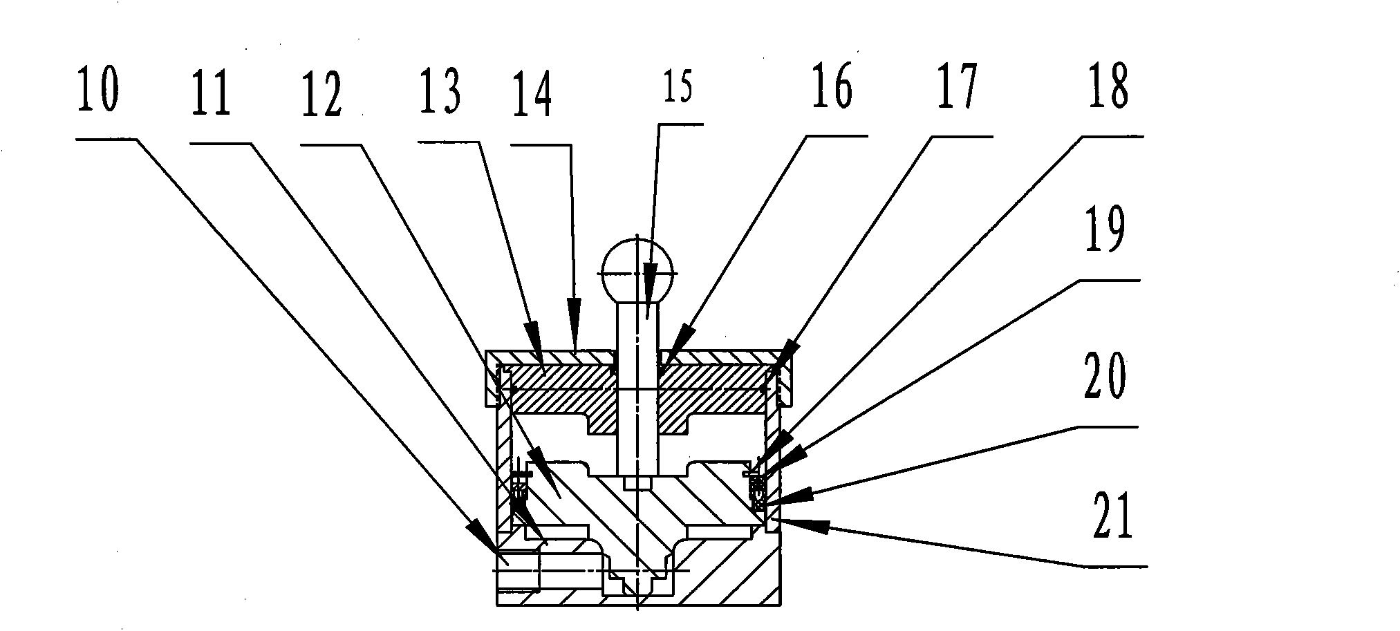
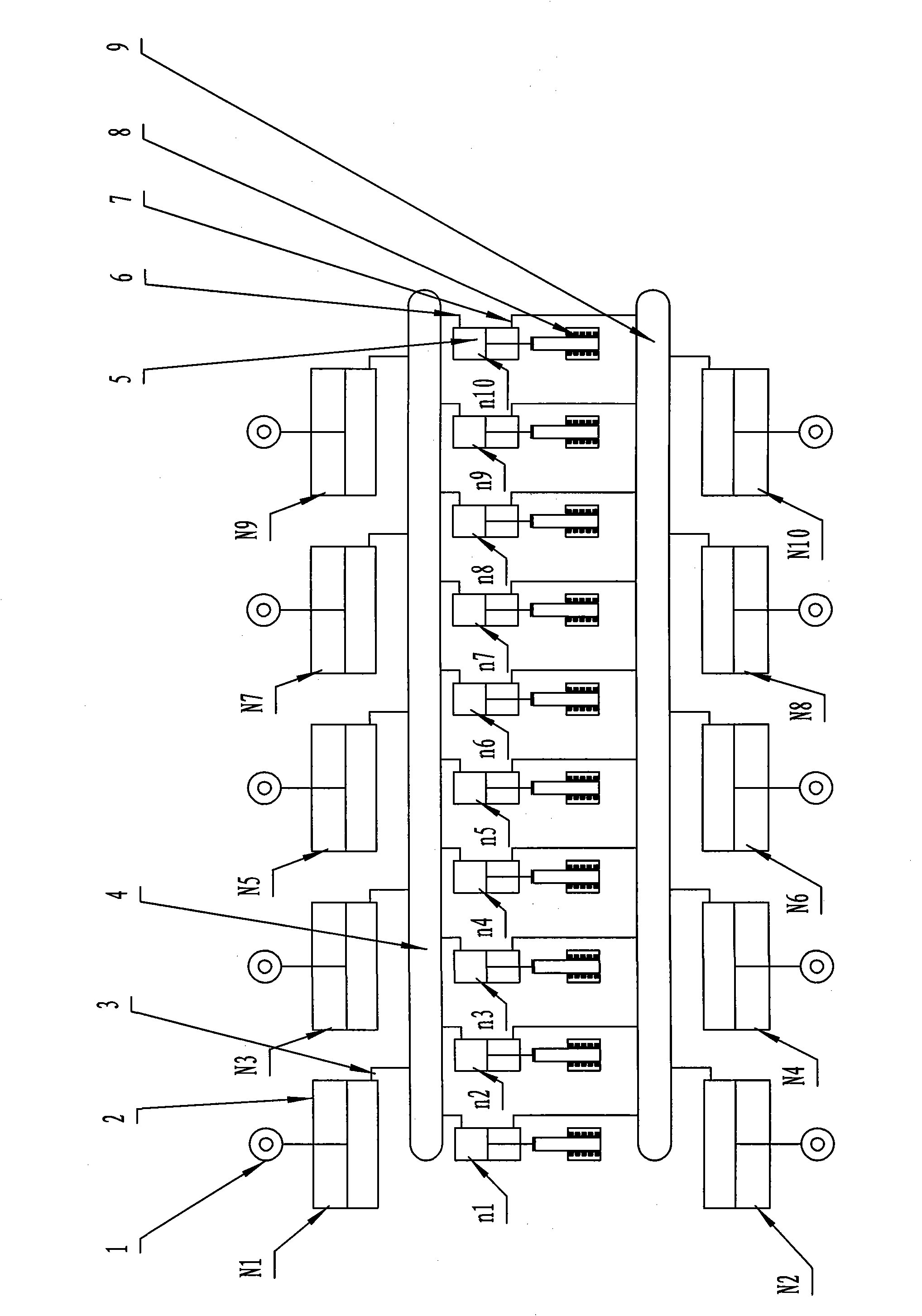
[0037] The use of the present invention is installed on the wheel of the motor vehicle. Figure 5 It is one of the installation diagrams of the present invention. In the figure, the single-acting piston cylinders N1-N8 are uniformly distributed in the radial direction of the hub 44 and connected with the hub 44 for motive power collection. Inwardly connect N1, N3, N5, N7 to the pressurized oil tank 4 from the single-acting oil circuit 3, and connect N2, N4, N6, N8 to the pressurized oil tank 9. The pressurized oil tank 4 is connected with the double-acting oil circuit 6 that drives the double-acting single-piston rod oil cylinder 5 (n1-n8) distributed uniformly in the radial direction. The pressurized oil tank 9 is connected with the second double-acting oil passage 7 of n1-n8. The pressurized oil tank is fixed on the wheel hub 44 . The tire 43 wraps radially uniform N1-N8 between the hub 44 and the tire 43 . After the tire is inflated, the anti-friction shock-absorbing cov...
Embodiment 2
[0039] The prime mover of the present invention adopts the single-acting spring reset cylinder 2.1 for prime mover acquisition, and the working machine adopts the driving single-acting spring reset cylinder 2.2. The installation of the power generation system with automatic return function of the present invention is as follows: Figure 10 Shown: in the figure, the original power collection single-acting spring return cylinder 2.1 (N1-N7) is evenly distributed in the radial direction outside the wheel hub 44 and connected with it. The inward single-acting oil passage 3 is connected to the pressurized oil tank 4 , and the pressurized oil tank 4 is fixed on the hub 44 . The drive single-acting spring return cylinder 2.2 (n1-n8) fixed on the hub 44 is radially evenly distributed and connected to the pressurized oil tank 4 respectively through 3, and the tire 43 wraps 2.1 (N1-N7) between the hub 44 and the tire 43 between. After the tire is inflated, the anti-friction shock abso...
Embodiment 3
[0041] The installation diagram of the double-acting power generation system of the present invention is as follows Figure 5 Shown: the installation structure is as follows Figure 14 As shown: when the tire rotates, the tire 43 is deformed by the gravity of the motor vehicle, the ball joint at the end of the piston rod of N1 is stressed, the piston pushes the hydraulic oil into the pressurized oil tank 4 through the single-acting oil circuit 3, and then passes through the first double-acting oil circuit 6 drives n1-n8 actions, that is, 8 groups of permanent magnet linear generators work once to generate electricity. The primary core 29, the primary winding 30 and the permanent magnet 35 are respectively driven by two driving double-acting single-piston cylinders 5 to move in opposite directions when the 8 groups of generators are working-to generate electricity. When N2 is working, the hydraulic oil enters the pressurized oil tank 9 through the single-acting oil circuit 3, ...
PUM
 Abstract
Description
Claims
Application Information
 - R&D
- Intellectual Property
- Life Sciences
- Materials
- Tech Scout
- Unparalleled Data Quality
- Higher Quality Content
- 60% Fewer Hallucinations
Browse by: Latest US Patents, China's latest patents, Technical Efficacy Thesaurus, Application Domain, Technology Topic, Popular Technical Reports.
© 2025 PatSnap. All rights reserved.Legal|Privacy policy|Modern Slavery Act Transparency Statement|Sitemap|About US| Contact US: help@patsnap.com


