Torque-excited rotary guide type jaw overrunning clutch and self-locking differential
An overrunning clutch and guided technology, which is applied in the field of mechanical transmission, can solve the problems of high price, doubled cost, and accelerated mechanical wear of the mating teeth, and achieves the effects of convenient processing, simplified structure, and reliable mating
- Summary
- Abstract
- Description
- Claims
- Application Information
AI Technical Summary
Problems solved by technology
Method used
Image
Examples
Embodiment 1
[0041] Embodiment 1: One-way overrunning clutch C1
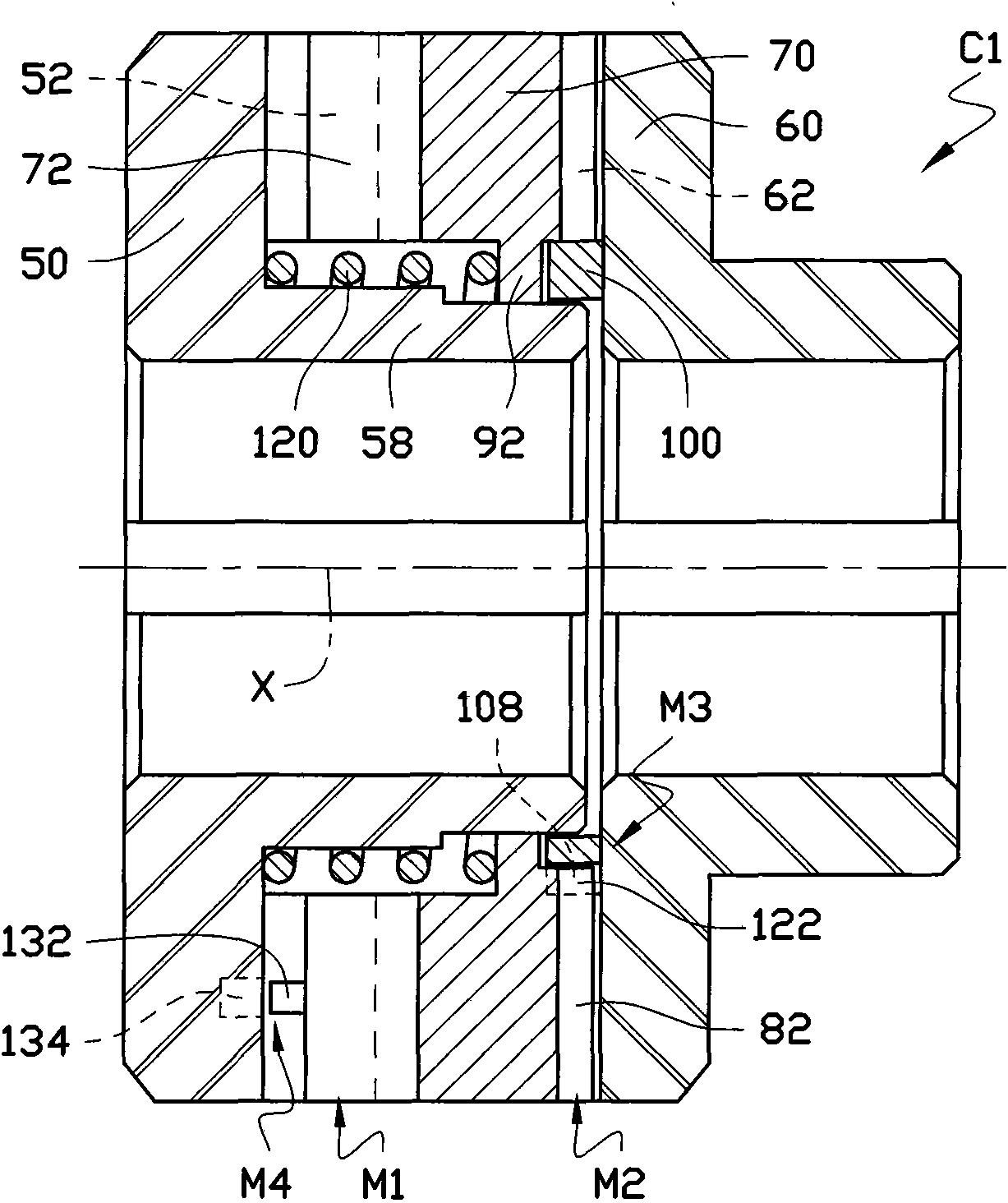
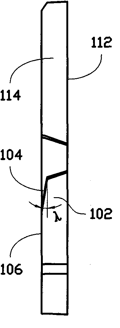
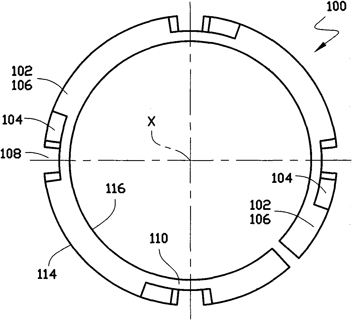
[0042] see figure 1 , 3, 4, the clutch C1 in the form of shaft-shaft transmission is the simplest embodiment according to the present invention. It includes a first rotating guide mechanism M1, which is an axial fitting mechanism including a first guide member 50 and an intermediary member 70 . Among them, the ring-shaped first guide member 50 fixed on the first rotating shaft (not shown) rotating around the axis X through a flat key has a circular tubular base 58 extending to the right end formed on the radially inner side, and a radially outer right end There are sawtooth-shaped first guide teeth 52 evenly distributed on the circumferential direction of the surface, and the teeth have a helical-toothed guide surface 54 and a non-guide surface 56 parallel to the axis X, see FIG. 4( a ). Correspondingly, on the left end surface of the intermediary member 70 that is vacantly sleeved on the cylindrical base body 58, there ar...
Embodiment 2
[0065] Embodiment 2: Two-way overrunning clutch C5
[0066] Compared Figure 9 and Figure 6 It can be seen that this embodiment is the result of the following major improvements to the clutch C3, that is, an orientation mechanism M5 and an actuating mechanism are added, and in order to correspond to two different circumferential working directions, the first rotation guide mechanism M1 The non-guiding surfaces 56 and 76 are changed to be 54b and 74b symmetrical to the guiding surfaces 54a and 74a; each blocking tooth 102 has two blocking working surfaces 104a and 104b circumferentially symmetrically; each auxiliary blocking tooth 122 is circumferentially symmetrical. It has two blocking working surfaces 124a and 124b symmetrically, and just spans two short guide teeth 82 in the circumferential direction, see FIG. 12 .
[0067]Wherein, the cylindrical cam type actuating ring 160 of the actuating mechanism is rotatably and axially fixed on the outwardly extending tubular base...
Embodiment 3
[0078] Embodiment 3: Dental self-locking differential D1
[0079] see Figure 13 , 14. The differential D1 is essentially an improved application in which two two-way overrunning clutches C5 are coupled axially and two intermediary members 70 are linked circumferentially.
[0080] Its main improvement is that the first guide teeth 52 are symmetrically arranged on the two end surfaces of the first guide member 50, and the differential case 190 replaces the cup-shaped shell-type force limiting element 188 to encapsulate the two rotating guide mechanisms integrally, and the elastic The element 120 acts optimally directly between the intermediate members 70a and 70b, the two pin-and-slot orientation mechanisms M5 are independent of the two re-separation assurance mechanisms M4 and merge into one linked orientation mechanism M5. see Figure 13 , 14, the orientation pin 140 of the orientation mechanism M5, which is arranged on the midpoint of the tooth top surface of the right end...
PUM
 Abstract
Description
Claims
Application Information
 - R&D
- Intellectual Property
- Life Sciences
- Materials
- Tech Scout
- Unparalleled Data Quality
- Higher Quality Content
- 60% Fewer Hallucinations
Browse by: Latest US Patents, China's latest patents, Technical Efficacy Thesaurus, Application Domain, Technology Topic, Popular Technical Reports.
© 2025 PatSnap. All rights reserved.Legal|Privacy policy|Modern Slavery Act Transparency Statement|Sitemap|About US| Contact US: help@patsnap.com


