Motorcycle engine

An engine and motorcycle technology, applied in engine components, machines/engines, mechanical equipment, etc., can solve the problem that lubricating oil can not meet the needs of engine lubrication and cooling, affect the reliability and service life of the engine, and increase the probability of the crankshaft being locked and other problems, to achieve the effect of eliminating excessive consumption of lubricating oil, compact structure, and avoiding the phenomenon of oil stringing.

Inactive Publication Date: 2011-01-12
CHONGQING LONCIN MOTOR
View PDF6 Cites 6 Cited by
  • Summary
  • Abstract
  • Description
  • Claims
  • Application Information

AI Technical Summary

Problems solved by technology

In terms of structure, it is as follows: the power chamber and the transmission chamber are connected, and a shared lubricating oil pool is formed at the lowest point in the chamber. The whole engine adopts a set of lubricating system. For the use in the environment, it is enough to meet the use requirements, but for the three-wheeled motorcycles with relatively harsh working conditions, the lubricating oil can no longer meet the normal lubrication and cooling needs of the engine. If the temperature of the transmission chamber is too high, It is prone to the phenomenon that the lubricating oil is consumed too quickly due to high temperature, and, because the transmission chamber will generate impurities during operation, these impurities enter the power chamber with the lubricating oil, making the lubricating oil in the power chamber unclean, increasing the The probability of the crankshaft being locked affects the reliability and service life of the engine

Method used


Image

  • Motorcycle engine
  • Motorcycle engine
  • Motorcycle engine

Examples


Embodiment Construction

[0023] The present invention will be further described below in conjunction with drawings and embodiments.

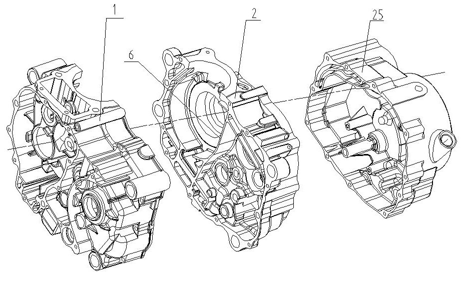
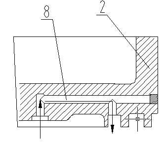
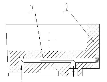
[0024] like Figure 1 to Figure 6 As shown, the motorcycle engine of the present invention has a left case body 1, a right case body 2 and a right cover 25, and the left case body 1 and the right case body 2 are butted together to form a crank case body. A first sealing rib 5 is provided between the power chamber 3 and the transmission chamber 4 of the left case 1, a second sealing rib 6 is provided between the power chamber 3 and the transmission chamber 4 of the right case 2, and the left case 1 and the right After the case body 2 and the box face are butted and assembled, the first sealing rib 5 and the second sealing rib 6 are joined together as an oil separation belt to completely separate the power chamber 3 and the transmission chamber 4 of the engine. The box body 2 is formed with mutually independent power chamber lubricating oil passage 7 and transmission cha...


PUM


Abstract

The invention provides a motorcycle engine. A sealing tendon is arranged between a power cavity and a transmission cavity of a left case and a right case, the sealing tendon is used as an oil separation belt to completely separate the power cavity and the transmission cavity of the engine after the assembly of the left case and the right case, the left case and the right case respectively form a power cavity lubrication oil way and a transmission cavity lubrication oil way which are mutually independent, the power cavity lubrication oil way is communicated with an oil sump at the bottom of the power cavity, and the transmission cavity lubrication oil way is communicated with an oil sump at the bottom of the transmission cavity; and two oil pumps are installed on the right case and are respectively communicated with the power cavity lubrication oil way and the transmission cavity lubrication oil way. By using the technical scheme, the invention realizes the separation of thermal engine lubrication oil and cold engine lubrication oil without changing the shape of the four-stroke engine and the position of the suspension interface of the traditional motorcycle, thereby being beneficial to improving the performance of the engine and prolonging the service life of the engine. The respective oil pump of the two independent lubrication systems can work reliably.

Description

technical field [0001] The present invention relates to engines, especially motorcycle engines. Background technique [0002] The lubricating system of the power chamber (heat engine part) and the transmission chamber (cold machine, that is, the gearbox transmission part) of the existing motorcycle four-stroke engine is combined, and the same lubricating oil is used. In terms of structure, it is as follows: the power chamber and the transmission chamber are connected, and a shared lubricating oil pool is formed at the lowest point in the chamber. The whole engine adopts a set of lubricating system. For the use in the environment, it is enough to meet the use requirements, but for the three-wheeled motorcycles with relatively harsh working conditions, the lubricating oil can no longer meet the normal lubrication and cooling needs of the engine. If the temperature of the transmission chamber is too high, It is prone to the phenomenon that the lubricating oil is consumed too ...

Claims


Application Information

Patent Timeline
Patent Type & Authority Applications(China)
IPC IPC(8): F02F7/00F01M1/02
Inventor 陈翔
Owner CHONGQING LONCIN MOTOR
Why Eureka
Try Eureka