Tunnel diffusion draught fan

A technology of ejector fan and wind tunnel, which is applied in the direction of wind engine, wind engine consistent with the wind direction, wind engine control, etc. It can solve the problems of increased average output time of the fan at high speed, inconvenient installation and maintenance, and large resource loss. , to achieve the effect of increasing the average flow velocity, reducing the cost of the tower, and reducing the proportion of investment

Inactive Publication Date: 2011-01-19
李平
View PDF6 Cites 12 Cited by
  • Summary
  • Abstract
  • Description
  • Claims
  • Application Information

AI Technical Summary

Problems solved by technology

The number of impellers depends on the needs. The working machine can be a generator or a water pump. The wind tunnel type diffuser injection fluid channel is used to improve the atmospheric air flow field and increase the speed of airflow entering the channel. Running in a closed fluid channel, the high-speed average output time of the fan increases. More importantly, the number of stages of impellers can be added along the direction of the fluid in the channel to fully capture the kinetic energy lost in the axial direction of the upper-stage impeller many times. Thereby the purpose of improving kinetic energy utilization rate and reducing the loss of atmospheric kinetic energy resources is achieved, thereby solving and making up for the problems and deficiencies of low kinetic energy utilization rate and large resource loss in the current technology. The impeller can be installed in the smallest diameter of the fluid channel to capture kinetic energy, so the diameter of the impeller is greatly reduced, which makes up for the excessive volume of the impeller and the high proportion of cost in the current fan design. Manufacturing, transportation , Installation and maintenance are inconvenient and costly defects and deficiencies

Method used


Image

  • Tunnel diffusion draught fan
  • Tunnel diffusion draught fan
  • Tunnel diffusion draught fan

Examples


Embodiment 1

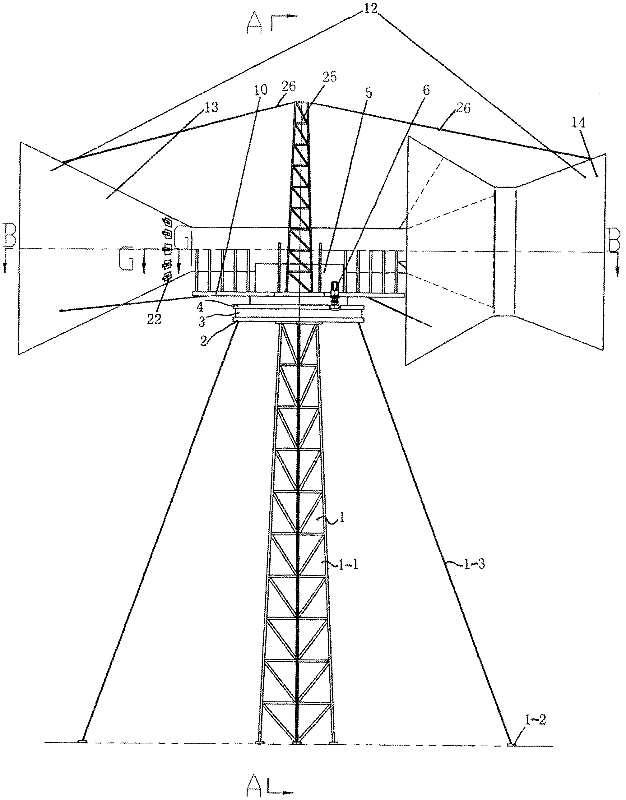
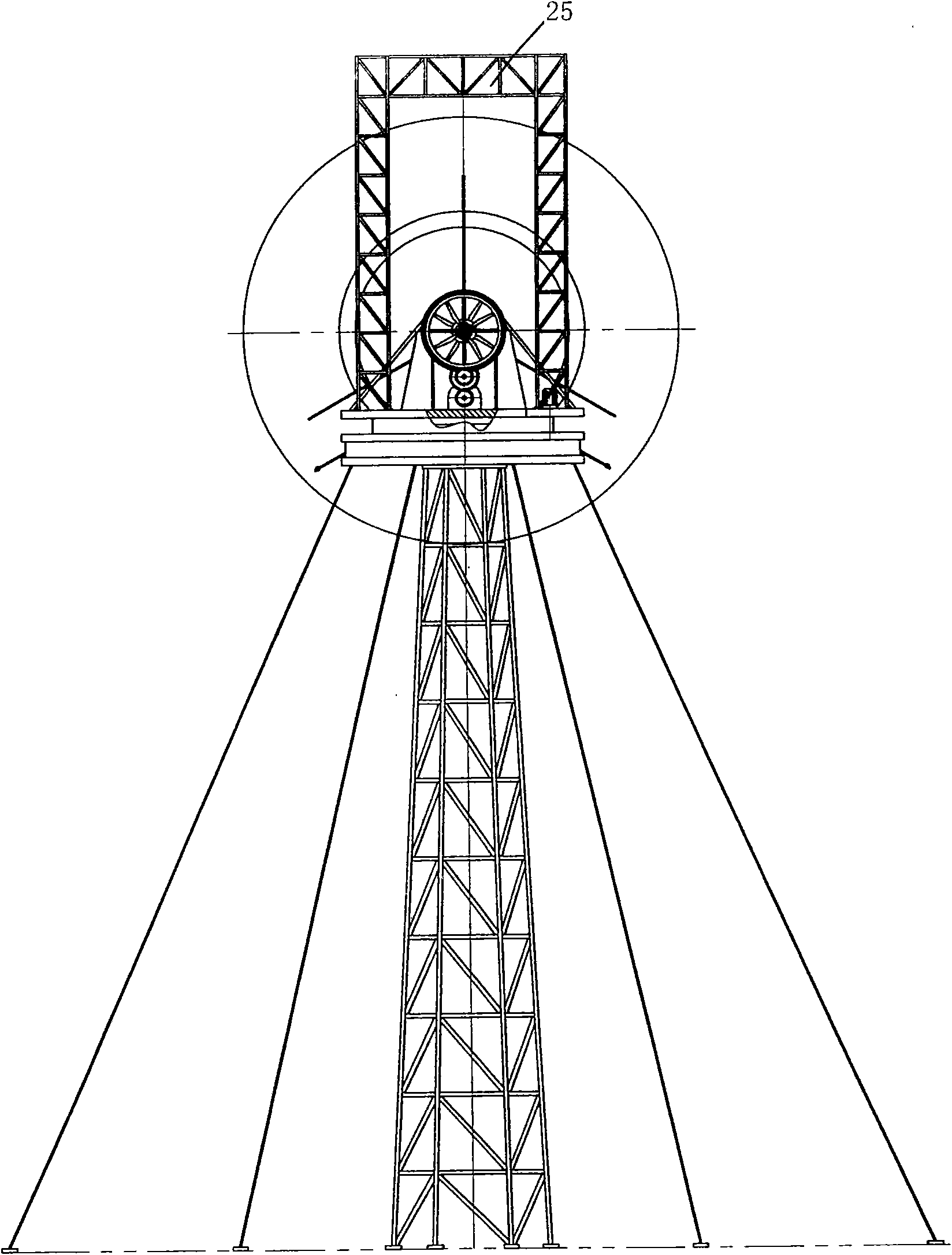
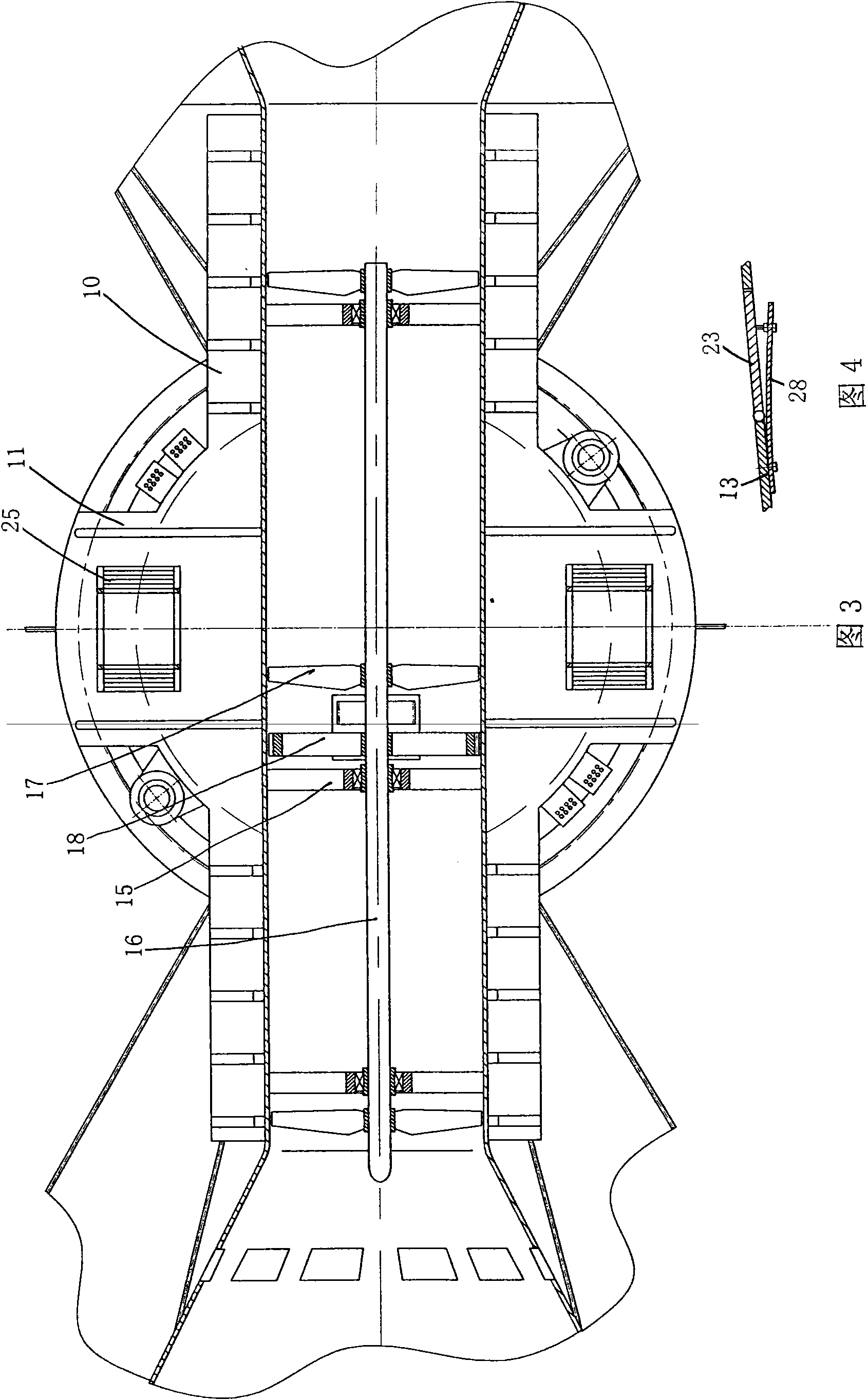
[0050] Figure 1 to Figure 10 Figure 1 of this embodiment is given. see Figure 1 to Figure 10 , the wind tunnel type diffuser and ejection fan in this embodiment includes a tower 1, a circular working platform 2 mounted on the top of the tower, a lower bearing plate 3 installed on the circular working platform, and a lower bearing plate located on the lower bearing plate. The upper bearing plate 4, the nacelle 5 installed on the upper bearing plate, the four yaw motor output shafts in the yaw device 6 installed on the upper bearing plate and the yaw teeth on the lower bearing plate Ring 7 meshes so as to drive the nacelle and the driving gear 8 that the upper load-bearing coil rotates around the yaw ring gear, and a plurality of yaw brakes 9 are arranged on the upper and lower load-bearing discs (see Figure 9 , Figure 10 ). A support bracket 10 is housed on the upper force plate. The support bracket is a rectangular frame with wings 11 on both sides (see Figure 8 ). ...

Embodiment 2

[0067] figure 2 Figure 2 of this embodiment is given. Embodiment 2 is basically the same as Embodiment 1. The difference is that there is no ejector.

[0068] The shape, structure, size, proportion, and material of the diffuser and ejector of the present invention must be determined, and in special cases or fan fluid passages are directly built on canyons, hillsides, special-shaped landforms, or other building objects without towers, etc. Circumstances can be adjusted accordingly. But as long as the diffuser or other artificial flow fields can achieve the technical and economic effect of increasing the speed of airflow diffusion.

[0069] In the present invention, the number of stages of impellers installed in the fluid channel can be determined according to actual needs. As long as it can achieve the effect of intensively capturing kinetic energy through the artificial flow field.

[0070] The number, orientation, and form of the constant-pressure hatches at the three-d...


PUM


Abstract

The invention discloses a tunnel diffusion draught fan, which comprises a tower, a worktable arranged on the top of the tower, a lower bearing disk arranged on the worktable, an upper bearing disk positioned on the lower bearing disk and a cabin arranged on the upper bearing disk, wherein the upper bearing disk is provided with a supporting bracket which is provided with a tunnel diffusion draught fluid channel with a round cross section; a diffuser is arranged in the tunnel diffusion draught fluid channel; a front diffusion and acceleration section three-dimensional channel, a three-dimensional fluid acting channel and a rear post-action air flow three-dimensional fluid channel, which are communicated in turn, are arranged in the diffuser; and the three-dimensional fluid acting channel is provided with at least two impellers along the axial direction of the fan, and a working machine positioned in the cabin is connected with the impellers through a transmission mechanism. The tunnel diffusion draught fan has high kinetic energy utilization rate and reduced cost and is convenient and safe in manufacturing, transportation, installation and maintenance.

Description

Technical field: [0001] The invention belongs to the field of wind power machinery. It is a wind tunnel diffuser that uses a diffuser injection method to increase the airflow velocity and capture kinetic energy in the same fluid channel, the same axial multi-stage impeller steps, improve the energy efficiency ratio, and reduce the loss of axial kinetic energy loss. Ejector fan. Background technique: [0002] Human beings have used wind energy for thousands of years. In the field of wind energy utilization, it has developed from early agricultural processing and pumping irrigation to today's thermal energy conversion and power generation. Due to the low power coefficient of the vertical axis resistance fan in the ancient east, it has almost no application value today. However, modern European vertical-axis lift fans are not suitable for use due to their prominent shortcomings such as large vibration and large negative impact on the ground. Therefore, in the field of moder...

Claims


Application Information

Patent Timeline
Patent Type & Authority Applications(China)
IPC IPC(8): F03D1/00F03D1/04F03D1/06F03D7/04
CPCY02E10/723Y02E10/721Y02E10/72Y02P70/50
Inventor 李平
Owner 李平
Why Eureka
Try Eureka