Multi-gain mode low-noise amplifier

A low-noise amplifier, multi-gain mode technology, applied in the field of electronics, can solve the problem of saturation of the post-stage circuit, and achieve the effect of high gain, high gain and low noise.

Inactive Publication Date: 2011-01-19
CHENGDU CORPRO TECH CO LTD
View PDF5 Cites 19 Cited by
  • Summary
  • Abstract
  • Description
  • Claims
  • Application Information

AI Technical Summary

Problems solved by technology

For example, for a GSM type receiver, the minimum power can be as small as -102 dBm, while the maximum signal power is

Method used

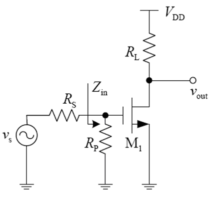
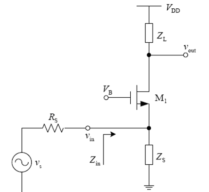

Image

  • Multi-gain mode low-noise amplifier
  • Multi-gain mode low-noise amplifier
  • Multi-gain mode low-noise amplifier

Examples


Example Embodiment

[0015] The multi-gain path low noise amplifier circuit according to the present invention includes a high-gain path, a low-gain path, an attenuation path, and a switch for controlling the on-off of the multi-gain path. Through the control of different gain paths, the high gain, low noise and high linearity performance of the low noise amplifier is realized. Among them, the high gain path adopts a source degenerate inductive low noise amplifier. The inductor is used to achieve input impedance matching and best noise matching. At the same time, a cascode structure is used to reduce the Miller effect of the transistor and obtain the best noise performance and maximum The gain. The low-gain path uses a similar structure to the high-gain path, and the low-noise amplifier achieves a compromise between gain, linearity, and noise performance through feedback. The attenuation path is composed of passive resistors or capacitors, and the best linearity can be obtained by attenuating the ...


PUM


Abstract

The invention discloses a multi-gain mode low-noise amplifier which comprises a high-gain channel mode, a low-gain channel mode, an attenuation channel mode and a switch for controlling the on/off mode switching of the multiple gain channels. By controlling the different gain channels, the invention realizes the high-gain, low-gain and attenuation modes in one circuit topology, realizes the high-gain, low-noise and high-linearity performance of the low-noise amplifier, and solves the problem that the circuit structure of any single mode can not simultaneously achieve optimal allocation effects in the aspects of gain, noise, linearity and other performance.

Description

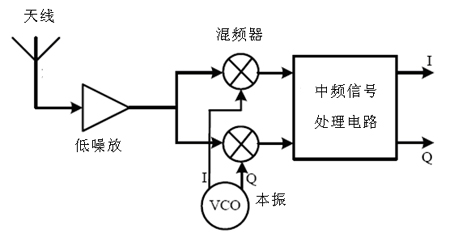
technical field [0001] The invention relates to the field of electronic technology, and is especially suitable for wireless transceiver systems. Background technique [0002] The low noise amplifier is usually the first stage of the receiver. Its function is to amplify the radio frequency signal under the premise of generating as low noise as possible to reduce the influence of the noise generated by the subsequent stages of the module on the signal. figure 1 A typical wireless receiver system is given. After the signal is received by the antenna, it is first amplified by a low-noise amplifier, then mixed with the local oscillator signal in the mixer (Mixer), and converted to an intermediate frequency signal after down-conversion. Subsequent processing. Among them, the local oscillator signal is provided by a voltage-controlled oscillator (VCO). [0003] As the first stage of the receiving system, the low-noise amplifier determines the noise level of the entire system. In ...

Claims


Application Information

Patent Timeline
IPC IPC(8): H03F1/26H03F3/45
Inventor 邵志刚
Owner CHENGDU CORPRO TECH CO LTD
Why Eureka
Try Eureka