
Power saving highl luminance integrated fluorescent lamp

An integrated technology for discharge lamps, applied in the field of integrated fluorescent lamps, can solve the problems of inability to clearly distinguish between luminescence and ionization, and achieve the effects of improving heat preservation, solving power consumption problems, and reducing power consumption

Active Publication Date: 2012-11-28
北京千树万树互联网科技有限公司
View PDF4 Cites 0 Cited by
  • Summary
  • Abstract
  • Description
  • Claims
  • Application Information

AI Technical Summary

Problems solved by technology

Previous researchers or technicians interpreted the detected light as a gas discharge, so they could not clearly distinguish between luminescence and ionization caused by the inelastic collision of moving electrons with gas atoms

Method used


Image

  • Power saving highl luminance integrated fluorescent lamp
  • Power saving highl luminance integrated fluorescent lamp
  • Power saving highl luminance integrated fluorescent lamp

Examples


Embodiment

[0158] Hereinafter, embodiments of the integrated fluorescent lamp of the present invention will be described in detail with reference to the drawings.

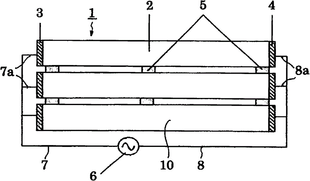
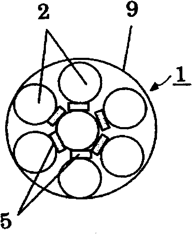
[0159] figure 1 It is an overall configuration diagram of the integrated fluorescent discharge lamp of the present invention in which seven fluorescent lamp tubes of the same tube diameter are bundled. In this integrated fluorescent lamp 1 , six fluorescent lamp tubes 2 are separated from each other by a predetermined interval through a spacer 5 and arranged in a bundle. Discharge space insulating electrodes 3 and 4 are formed on the left and right ends of the above-mentioned fluorescent lamp tube 2 . The discharge space insulating electrodes 3 and 4 are electrically insulated from the discharge space 10 formed inside the fluorescent tube 2 and filled with the discharge gas. Parallel portions 7a, 8a are arranged on the discharge space insulating electrodes 3, 4 of the seven fluorescent lamp tubes 2, and wirings 7, 8 for app...


PUM


Abstract

An integrated fluorescent lamp is provided with fluorescent lamp tube groups which are bundle-arranged by making tube axes parallel, a spacer separating adjacent fluorescent lamp tubes at prescribed intervals, and a parallel connection part connecting the fluorescent lamp tube groups in parallel. Electrodes on both ends of the fluorescent lamp tube are constituted of discharge space insulation-type electrodes which are electrically insulated from an inner discharge space. When high frequency voltage is applied to the parallel connection parts at both ends, discharge gas is ionized on electrons and positive ions, and a third generation electron source (called just as electron source) and a positive ion source are formed near the discharge space insulation-type electrodes. The fluorescent lamp tubes can be kept to 40 to 45 DEG C being a discharge optimum temperature by installing a heat keeping tube surrounding the integrated fluorescent lamp and heat keeping end pars at upper and lowerends. Even if all the tubes are simultaneously lighted, power consumption can be reduced and high luminance emission proportional to the number of tubes is realized. When the third generation electron source is used, the problem of electrode voltage drop and sputtering is solved.

Description

technical field [0001] The present invention relates to a fluorescent discharge lamp, which uses a plurality of fluorescent discharge lamp tubes coated with a fluorescent film on the inner surface of the glass tube. More specifically, the present invention provides an integrated fluorescent discharge lamp, which can greatly reduce power consumption Moreover, high-brightness luminescence can be realized, and the discarded fluorescent lamp tubes whose service life has expired can be recycled. Background technique [0002] Outline Description of Existing Fluorescent Discharge Lamp Tubes [0003] In recent years, with the deepening of the global warming effect, carbon dioxide emissions have become a worldwide problem. One of the reasons for the large emissions of carbon dioxide is the emission of carbon dioxide from power plants using fossil fuels. Turn the darkness of night into daytime brightness (an average of 10 per unit area per unit time 22 photons), will use a lot of p...

Claims


Application Information

Patent Timeline
Patent Type & Authority Patents(China)
IPC IPC(8): F21S2/00H01J65/00F21Y103/00
CPCH01J65/046
Inventor 小泽隆二加藤正利原田将弘
Owner 北京千树万树互联网科技有限公司
Learn More