
Method for the production of permanent magnets and a permanent magnet

A manufacturing method and technology of permanent magnets, which are applied in the manufacture of permanent magnets, inductors/transformers/magnets, magnetic objects, etc., can solve the problems of poor magnetic properties, low production efficiency, and troublesome disposal, and achieve strong corrosion resistance, low cost effect

Active Publication Date: 2013-03-06
ULVAC INC
View PDF1 Cites 0 Cited by
  • Summary
  • Abstract
  • Description
  • Claims
  • Application Information

AI Technical Summary

Problems solved by technology

However, when the sintered magnet is transported for Ni plating after sintering, it may react with oxygen or water, and the handling is troublesome.
In addition, the production efficiency is low due to the formation of a protective film through multiple processes such as surface cleaning and Ni plating.
On the other hand, after the sintered magnet is obtained, the sintered magnet is sometimes machined into a predetermined shape in order to trim it into a finished product. However, this processing causes defects (cracks, etc.) and distortion in the crystal grains of the sintered magnet, and the magnetic properties are significantly changed. Poor, so it is necessary to increase or restore the magnetization and coercive force according to the use of the product

Method used


Image

  • Method for the production of permanent magnets and a permanent magnet
  • Method for the production of permanent magnets and a permanent magnet
  • Method for the production of permanent magnets and a permanent magnet

Examples


Embodiment 1

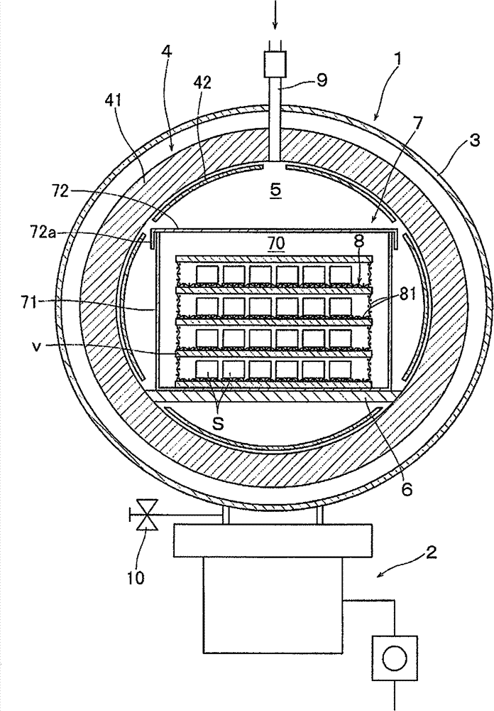
[0065] In Example 1, with figure 1 In the vacuum vapor treatment apparatus 1 shown in , the permanent magnet M is obtained by performing the first step and the second step on the sintered magnet S below. For the sintered magnet S, a commercially available 40H sintered magnet was purchased (composition ratio:

[0066] 28.5(Nd+Pr)-3Dy-0.05Co-0.05Cu-0.01Zr-0.05Ga-1.1B-Bal.Fe), processed into a cube of 10×10×10mm, and cleaned the surface.

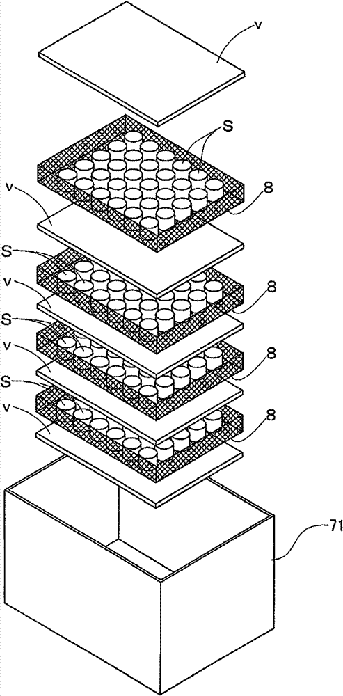
[0067] Next, use figure 1 The shown vacuum steam treatment apparatus 1 applies vacuum steam treatment to the sintered magnets S (five at a time) produced separately as described above. In this case, using 5 mm thick Dy (purity 99.5%) as the metal evaporation material v, a total of 5 g of Dy was placed on the bottom surface of a treatment box made of Ta, and a sintered magnet S was placed on the upper side of Dy. Gaskets made of it. Then the pressure in the vacuum chamber 3 reaches 10 -5 After Pa, the heating device 4 was operated, the temp...

Embodiment 2

[0072] In Example 2, with figure 1 In the vacuum vapor treatment apparatus 1 shown in , the permanent magnet M is obtained by performing the first step and the second step on the following sintered magnet S. As the sintered magnet S, a commercially available 45H sintered magnet was purchased (composition ratio:

[0073] 25.5(Nd+Pr+Ho)-3.5Dy-1Co-0.15Cu-0.15Ti-0.05Sn-0.95B-Bal.Fe), processed into a cube of 7×7×7mm, and cleaned the surface.

[0074] Next, use figure 1 The vacuum vapor treatment apparatus 1 shown in , applies vacuum vapor treatment to the sintered magnets S (10 pieces at a time) prepared separately as described above. In this case, using 0.5 mm thick Dy (purity 99.5%) as the metal evaporation material v, a total of 5 g of Dy was placed on the bottom surface of a treatment box made of Ta, and a sintered magnet S was placed on the upper side of Dy. Gaskets made of Ta. Then the pressure in the vacuum chamber 3 reaches 10 -4 After Pa, the heating device 4 was ope...


PUM

PropertyMeasurementUnit
thicknessaaaaaaaaaa
particle sizeaaaaaaaaaa
thicknessaaaaaaaaaa

Abstract

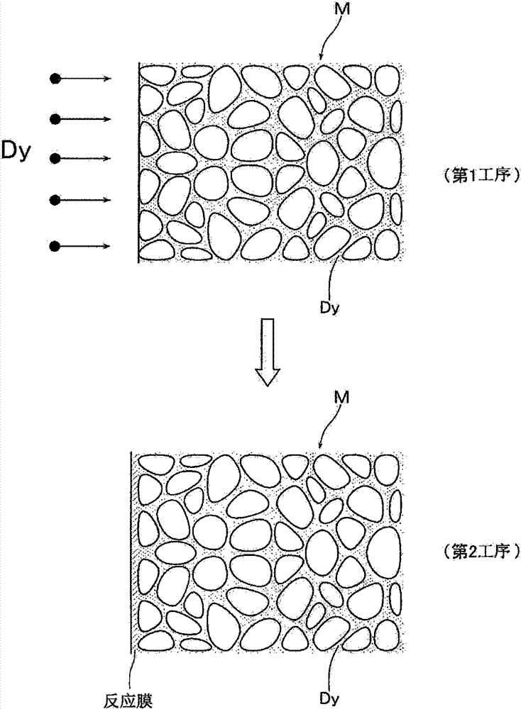
Provided is a method for the production of permanent magnets whereby permanent magnets having effectively improved or restored magnetic characteristics such as coercive force which are corrosion resistant and weather resistant can be produced at low cost and in a way which is suitable for mass production. An iron - boron - rare earth sintered magnet and a metal vaporization material which contains at least one of Dy and Tb are arranged in a treatment chamber and heated to vaporization. An inert gas is introduced into the treatment chamber where the sintered magnet has been arranged while the metal vaporization material is being vaporized. Metal atoms are deposited while the quantity of vaporized metal atoms being supplied to the surface of the sintered magnet is adjusted by controlling the partial pressure of the inert gas and the metal atoms are diffused into the crystal grain boundaries and / or crystal grain boundary phase of the sintered magnet before a thin film comprised of deposited metal atoms is formed. Cold gas is then introduced into the treatment chamber where the sintered magnet has been arranged and a reaction gas is introduced while the treatment chamber is being cooled, and the surface of the sintered magnet is covered with a reaction film and set in a fixed state.

Description

technical field [0001] The present invention relates to a method for manufacturing a permanent magnet, in particular to a method for diffusing Dy or Tb into the grain boundaries and / or grain boundary phases of Nd-Fe-B based sintered magnets without the need for a protective film formed by Ni electroplating A method for manufacturing a high-performance permanent magnet and a permanent magnet manufactured by the method. Background technique [0002] Nd-Fe-B sintered magnets (so-called neodymium magnets) are composed of a combination of iron, Nd, and B elements that are cheap and abundant and can be stably provided, so they can be manufactured cheaply and have high magnetic properties (maximum magnetic energy Its volume is about 10 times that of ferrite-based magnets), and it is used in various products such as electronic equipment, and is also used in electric motors and engines for hybrid vehicles, and its usage is increasing. [0003] Such a sintered magnet is mainly produc...

Claims


Application Information

Patent Timeline
Patent Type & Authority Patents(China)
IPC IPC(8): H01F41/02H01F1/053
CPCH01F1/0577H01F41/0293H01F41/026
Inventor 永田浩新垣良宪
Owner ULVAC INC
Learn More