
Integrated detector for micro-force micro-displacement measurement system

A measurement system and detector technology, applied in the field of integrated detectors, can solve the problems of low displacement and micro force measurement accuracy, inconvenient installation and system integration, complex optical system structure, etc. The effect of system volume

Inactive Publication Date: 2011-01-26
TSINGHUA UNIV
View PDF5 Cites 24 Cited by
  • Summary
  • Abstract
  • Description
  • Claims
  • Application Information

AI Technical Summary

Problems solved by technology

AFM adopts Cantilever and Position Sensitive Detector (PSD) for detection, and uses the optical lever amplification principle to convert the bending deformation of the cantilever under force into the change of the spot position on the PSD, thereby Realize high-precision micro-force detection, but the optical system has complex structure, high cost, and is not easy to install and system integration
There are also attempts to integrate piezoelectric strain gauges with AFM probes. Although the system is relatively compact, due to the influence of thermal and electrical noise, the measurement accuracy of displacement and micro force is lower than that of optical measurement methods.

Method used


Image

  • Integrated detector for micro-force micro-displacement measurement system
  • Integrated detector for micro-force micro-displacement measurement system
  • Integrated detector for micro-force micro-displacement measurement system

Examples


Embodiment Construction

[0031] In order to make the above objects, features and advantages of the present invention more comprehensible, the present invention will be further described in detail below in conjunction with the accompanying drawings and specific embodiments.

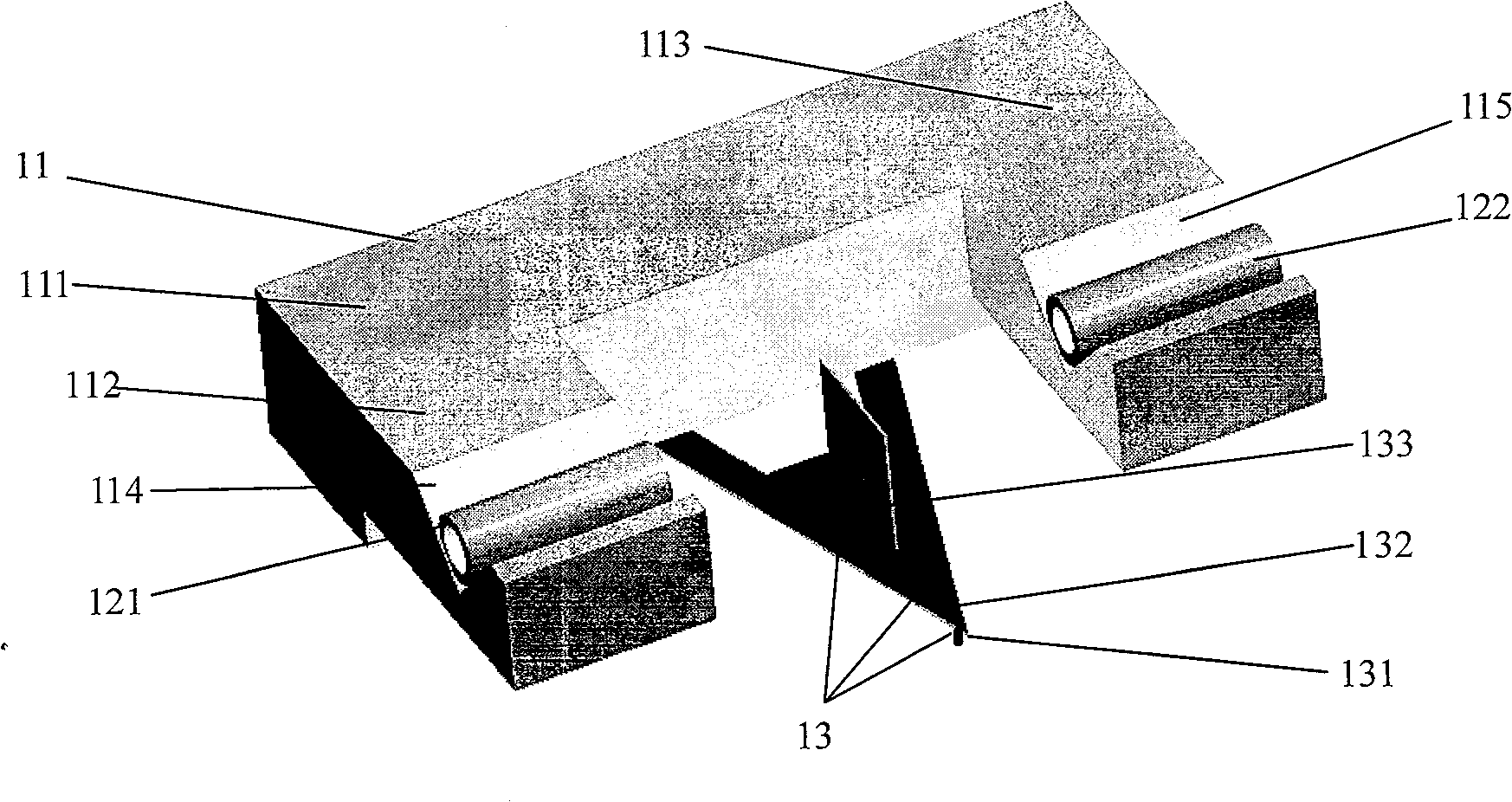
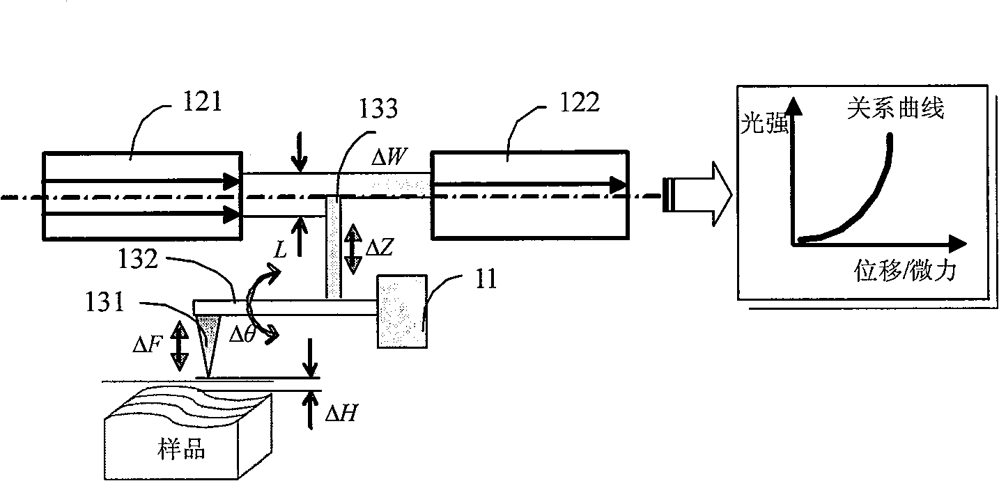
[0032] refer to figure 1 , which shows a structure diagram of an embodiment of an integrated detector for a micro-force and micro-displacement measurement system according to the present invention, the detector includes: a fixing frame 11, an optical fiber sensing module and a micro-detecting module 13;

[0033] The fixed frame 11 is a U-shaped fixed frame, including a base 111, and a symmetrical left arm 112 and a right arm 113 located at both ends of the base; the left arm is provided with a left V-shaped groove 114, and the right arm There is a right V-groove 115 on the top;

[0034] The optical fiber sensing module includes: a transmitting optical fiber 121 and a receiving optical fiber 122, which are used to detect changes i...


PUM

PropertyMeasurementUnit
Thicknessaaaaaaaaaa

Abstract

The invention provides an integrated detector for a micro-force micro-displacement measurement system, which comprises a mounting bracket, an optical fiber sensing module and a micro-detection module, wherein the mounting bracket is U-shaped, and comprises a pedestal, a left arm and a right arm; the left arm is provided with a left V-shaped groove, while the right arm is provided with a right V-shaped groove; the optical fiber sensing module is used for detecting the variations of power of light incident to receiving optical fibers from emitting optical fibers; the emitting optical fibers are arranged in the left V-shaped groove of the mounting bracket, while the receiving optical fibers are arranged in the right V-shaped groove of the mounting bracket; the emitting optical fibers are coaxial with the receiving optical fibers; the micro-detection module comprises a microprobe, a micro-cantilever and a translational plate, and is used for changing the power of light incident to the receiving optical fibers in a way that the micro-cantilever drives the translational plate to produce vertical displacement according to the variations of the position of the microprobe on the surface of a sample; and the mounting bracket and the micro-detection module are machined into integrated firmware by using a micro-electromechanical system (MEMS) process. The integrated detector provided by the invention has the characteristics of simple realization, relatively lower cost and relatively higher detection accuracy.

Description

technical field [0001] The invention relates to the technical field of precision detection, in particular to an integrated detector used in a micro-force and micro-displacement measurement system. Background technique [0002] The development trend of high integration and high performance of electronic products and the development of Micro Electro Mechanical Systems (MEMS) technology and applications have put forward higher and higher requirements for ultra-precision surface and micro-nano structure detection, which has driven ultra- The rapid development of fine surface micro-nano measurement technology. Micron and nanoscale objects are fragile. In the process of state monitoring and application operation, on the one hand, it is necessary to precisely monitor the displacement state. At the same time, in order to ensure the smooth operation, micro force detection and control also play a very important and necessary role. Therefore, micro displacement and The integrated meas...

Claims


Application Information

Patent Timeline
IPC IPC(8): G01L1/24G01B11/02B81B3/00B81C1/00
Inventor 李玉和胡小根
Owner TSINGHUA UNIV
Learn More