Method for preparing metal composite material bonding interface separated sample

A metal composite material, material testing machine technology, applied in the field of metal composite materials

Active Publication Date: 2011-01-26
725TH RES INST OF CHINA SHIPBUILDING INDAL CORP
View PDF1 Cites 16 Cited by
  • Summary
  • Abstract
  • Description
  • Claims
  • Application Information

AI Technical Summary

Problems solved by technology

[0003] The technical problem to be solved by the present invention is to provide a method for preparing a metal composite material bonding interface separation sample to solve the problem of completely separating the bonding interface of the metal composite material

Method used


Image

  • Method for preparing metal composite material bonding interface separated sample
  • Method for preparing metal composite material bonding interface separated sample
  • Method for preparing metal composite material bonding interface separated sample

Examples


Embodiment 1

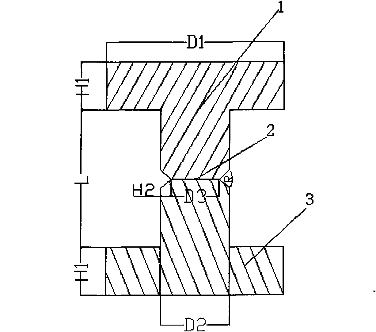
[0021] The material combination is 1060 / TA2 aluminum-titanium bimetallic composite bonded interface separation sample, the thickness of the clad metal 1060 and base metal TA2 of the metal composite is 12mm, processed by lathe figure 1 For the sample shown, D1=25mm, D2=14mm, H1=8mm, D3=6mm, L=8mm, angle R=30° of the V-shaped groove, height H2=4mm, use a 50-ton universal material testing machine to break the test In this way, the binding interface was completely separated, and the useful part was cut out. The morphology, microdomain composition and crystal structure of the binding interface were studied with a JSM-35C scanning electron microscope and a NEOPHOT1 metallographic microscope.

Embodiment 2

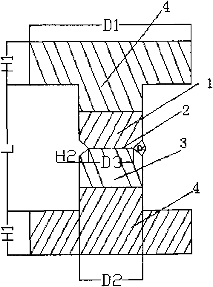
[0023] Prepare the stainless steel-steel bimetallic composite material combined interface separation sample with the material combination of 321 / Q370, the thickness of the clad metal 321 and the base metal Q370 of the metal composite material are 3mm and 6mm respectively, processed by a lathe figure 2 The sample shown is stainless steel 321 with a length of 15mm welded on the multilayer, Q370 with a length of 12mm welded on the base layer, D1=20mm, D2=10mm, H1=5mm, D3=6mm, L=20mm, the angle of the V-shaped groove R=90°, height H2=2mm, the sample was pulled off with a 50-ton universal material testing machine, the bonding interface was completely separated, and useful parts were cut out, and the structure of the bonding interface was studied with a JSM-35C scanning electron microscope and a NEOPHOT1 metallographic microscope Morphology, domain composition, and crystal structure.

Embodiment 3

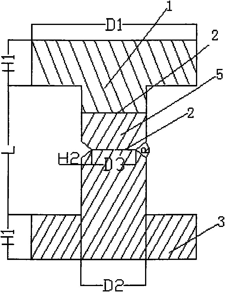
[0025] Prepare the aluminum alloy-aluminum-steel three-layer metal composite material 1060 / CCSB bonded interface separation sample whose material combination is 5083 / 1060 / CCSB. 8mm, 20mm, processed by lathe image 3 The sample shown, D1=15mm, D2=6mm, H1=10mm, D3=4mm, L=20mm, the angle R=45° of the V-shaped groove, the height H2=1mm. In this way, the binding interface was completely separated, and the useful part was cut out. The morphology, microdomain composition and crystal structure of the binding interface were studied with a JSM-35C scanning electron microscope and a NEOPHOT1 metallographic microscope.


PUM

PropertyMeasurementUnit
thicknessaaaaaaaaaa
thicknessaaaaaaaaaa
diameteraaaaaaaaaa

Abstract

The invention introduces a method for preparing a metal composite material bonding interface separated sample. The method comprises the following steps of: sampling from an entire metal composite material plate; machining the sample to be dumbbell-shaped along thickness direction, wherein the thickness directions of base layer metal and composite layer metal are both the length direction of the dumbbell-shaped sample; placing the bonding interface of the metal composite material at a middle position of the dumbbell-shaped sample; forming a V-shaped groove on the dumbbell-shaped sample; overlapping a bottom cross line of the V-shaped groove with a metal composite material bonding interface line; snapping the bonding interface with a 50-ton universal testing machine to completely separate the bonding interface of the metal composite material; and cutting the sample according to testing requirements. By the method, the bonding interface of the metal composite material with small thickness can be completely separated or a certain bonding interface of a multi-layer metal composite material can be completely separated, so that the problem of difficult complete separation of the metal composite material bonding interface is solved.

Description

technical field [0001] The invention relates to a technique in the field of metal composite materials, in particular to a method for preparing a metal composite material bonding interface separation sample. Background technique [0002] Explosive welding is a metal processing method that uses explosives as the energy source, and under the action of the explosive explosion load, the clad metal collides with the base metal at high speed and is firmly connected together. Metal composite materials overcome the limitations of single materials in terms of functions (such as anti-corrosion, high strength, etc.), and are widely used in petrochemical, electric power, metallurgy, shipbuilding, aerospace, nuclear industry and other fields. Because the bonding interface of metal composite materials is a metallurgical bond, the usual methods cannot completely separate the interface, so that the research on the microstructure information such as the microstructure, microdomain composition...

Claims


Application Information

Patent Timeline
Patent Type & Authority Applications(China)
IPC IPC(8): G01N1/28G01N19/04
Inventor 岳宗洪侯发臣徐宇皓
Owner 725TH RES INST OF CHINA SHIPBUILDING INDAL CORP
Why Eureka
Try Eureka