Solid crystal machine head bonding mechanism

A technology of crystal bonder and LED crystal bonder, which is applied in semiconductor/solid-state device manufacturing, electrical components, circuits, etc., can solve problems such as high cost and complex drive structure, and achieve long service life, cost reduction, and fewer components Effect

Inactive Publication Date: 2011-01-26
SHENZHEN WISDOW REACHES IND
View PDF8 Cites 22 Cited by
  • Summary
  • Abstract
  • Description
  • Claims
  • Application Information

AI Technical Summary

Problems solved by technology

[0008] The purpose of the present invention is to overcome the disadvantages of complex driving structure and high cost of the crystal-taking arm of the crystal-bonding machine in the above-mentioned prior art, and provide a simple-structure, easy-to-adjust, low-cost head-bonding mechanism of the crystal-bonding machine

Method used


Image

  • Solid crystal machine head bonding mechanism
  • Solid crystal machine head bonding mechanism
  • Solid crystal machine head bonding mechanism

Examples


Embodiment Construction

[0025] Below in conjunction with accompanying drawing, the present invention is described in further detail;

[0026] Implementation benefit one:

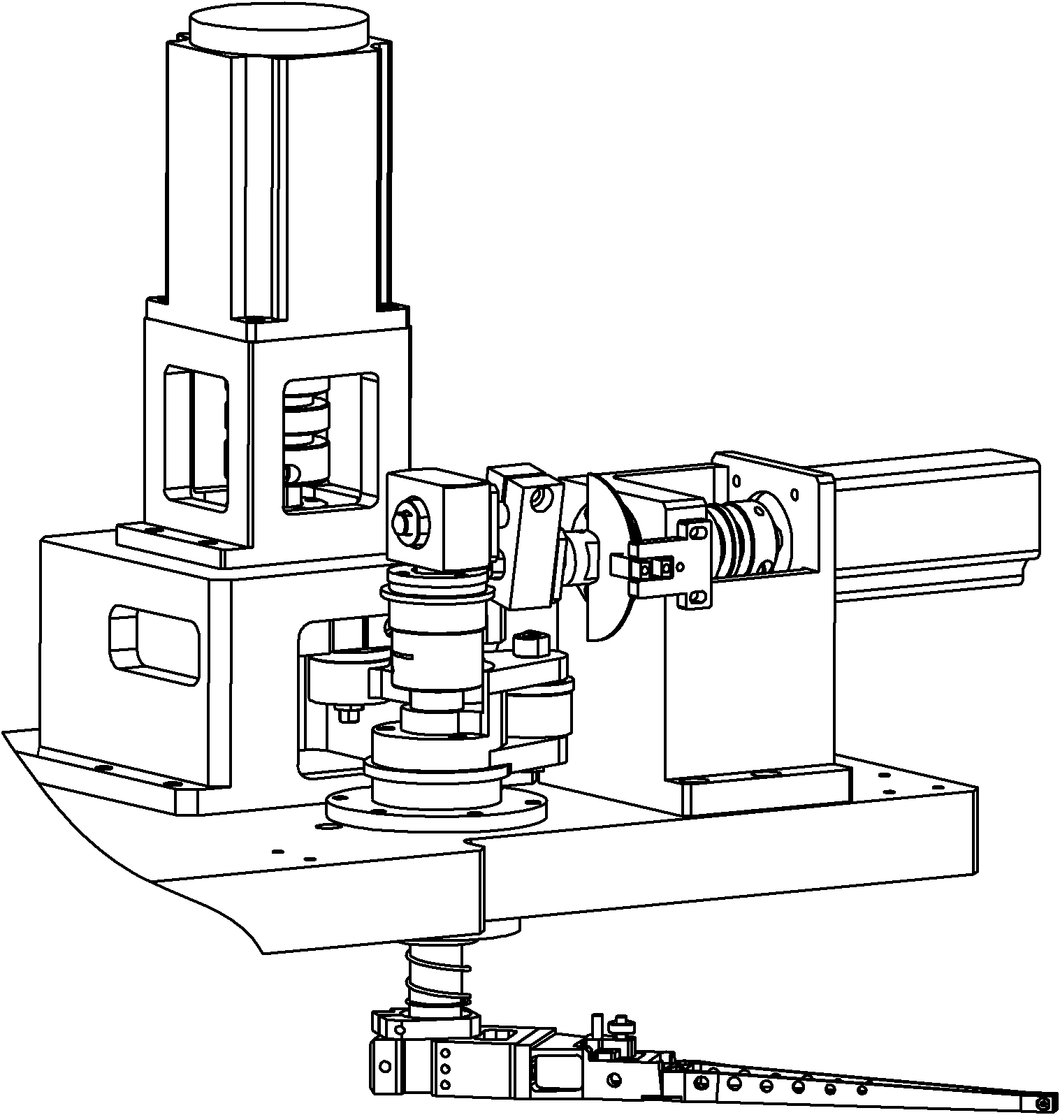
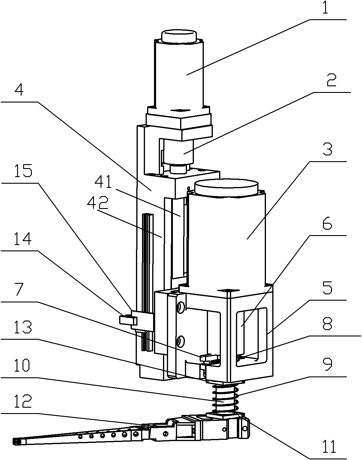
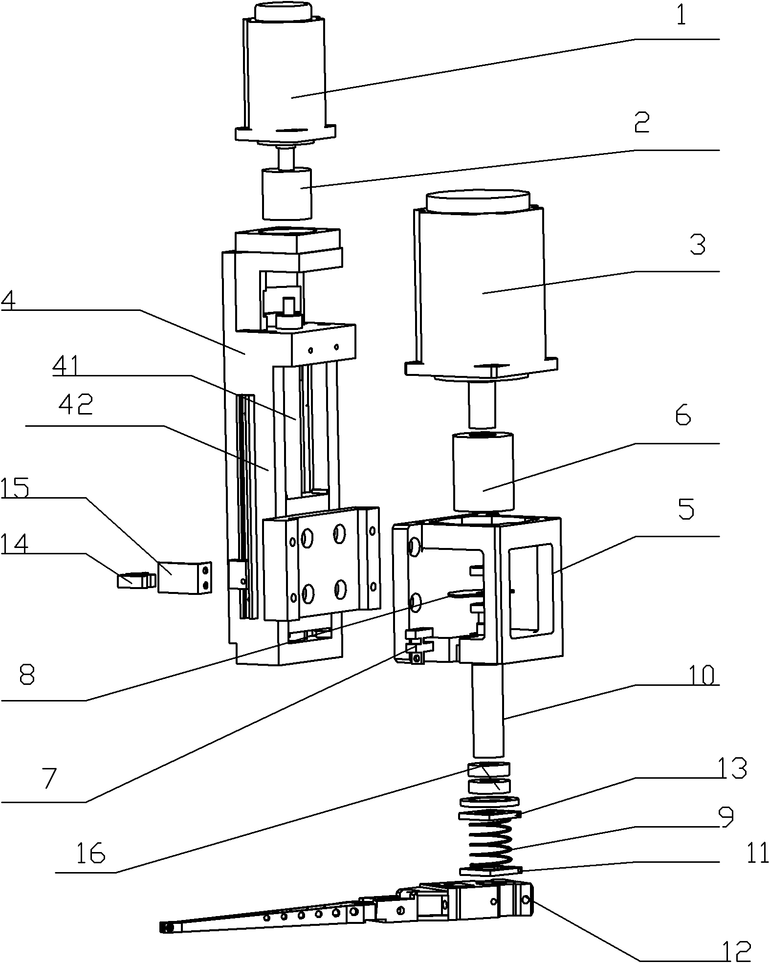
[0027] combine figure 2 , image 3 As shown, it is the overall structural combination diagram and explosion diagram of the die bonding machine head of the present invention, a die bonding machine head mechanism, including a crystal fetching arm drive control device and a crystal fetching arm, and the crystal fetching arm drive control device drives the crystal fetching arm movement, the crystal extraction arm drive control device includes a vertical drive control device and a rotation drive control device, and the rotation drive control device is installed on the up and down drive control device. The up and down drive control device includes a servo motor 1, a shaft coupling 2, and an integrated actuator 4, and the servo motor 1 drives the integrated actuator 4 to move up and down through the shaft coupling 2. The integrated ac...


PUM


Abstract

The invention provides a solid crystal machine head bonding mechanism. The mechanism comprises a crystal fetching arm drive control device and a crystal fetching arm, wherein the crystal fetching arm drive control device drives the crystal fetching arm to move. The crystal fetching arm drive control device comprises an up and down drive control device and a rotary drive control device, wherein the rotary drive control device is arranged on the up and down drive control device. The up and down drive control device comprises a servo motor, a coupler and an integral actuator, wherein the servo motor drives the integral actuator to move up and down through the coupler; the rotary drive control mechanism comprises a servo motor, a coupler and a rotary shaft; and the servo motor drives the rotary shaft to rotationally move through the coupler. The mechanism changes the traditional way of driving the crystal arm to rotate through the transmission of other parts, simplifies the mechanism of a head bonding drive control device and reduces cost.

Description

technical field [0001] The invention relates to a bonding head mechanism on a crystal bonding machine, in particular to a bonding head on a LED crystal bonding machine. Background technique [0002] LED crystal bonding machine is one of the key mechanical equipment necessary for the post-packaging process on the LED production line. Its mechanical parts include state head assembly, thimble assembly, wafer table assembly, optical system, oxide dispensing assembly and rotary positioning mechanism assembly. [0003] The crystal bonding process of LED crystal bonding machine is: the substrate or PCB is transferred to the working position of the fixture by manual or feeding mechanism, and the glue dispensing mechanism first dispenses the substrate or PCB at the position where the chip needs to be bonded, and then takes the crystal The arm moves from the origin position to the position where the wafer is sucked. The wafer is placed on the expander wafer tray supported by the film...

Claims


Application Information

Patent Timeline
IPC IPC(8): H01L33/00H01L21/68
Inventor 王鸿罗会才陈小宇梁杰坤
Owner SHENZHEN WISDOW REACHES IND
Why Eureka
Try Eureka