Waste heat recovery device

A waste heat recovery device and superheater technology, which is applied in waste heat treatment, lighting and heating equipment, furnaces, etc., can solve the problems of over-temperature tube explosion, tube explosion, and allowable stress reduction, so as to reduce the fluctuation range of working conditions and reduce The effect of ash on the heated area, preventing drift and eddy currents

Inactive Publication Date: 2011-02-02
JIANGNAN BOILERS & PRESSURE VESSELS ZHANGJIAGANG
View PDF5 Cites 2 Cited by
  • Summary
  • Abstract
  • Description
  • Claims
  • Application Information

AI Technical Summary

Problems solved by technology

Since the high-temperature flue gas produced in the acid production process contains a large amount of dust particles, when the high-temperature flue gas with a large ash content scours the tube bundles on the heating surface of the superheater horizontally, it is easy to cause the tube wall of the superheater to wear and accumulate dust. Thermal coefficient, and it is easy to cause tube explosion, affecting the safe production of sulfuric acid
In addition, in the acid waste heat recovery system, when the process load changes, the working condition of the superheater is unstable. When the metal temperature exceeds the allowable limit temperature, the internal structure of the metal structure changes, which reduces the allowable stress and produces plasticity. Deformation can also easily lead to over-temperature explosion
Therefore, the explosive tube of the superheater has always been an insurmountable problem in the waste heat recovery system of the acid production process

Method used


Image

  • Waste heat recovery device
  • Waste heat recovery device

Examples


Embodiment Construction

[0014] The present invention will be further described below in conjunction with the accompanying drawings and embodiments, wherein the positional relationship of "up" and "down" described in this description corresponds to the positional relationship between up and down shown in the drawings.

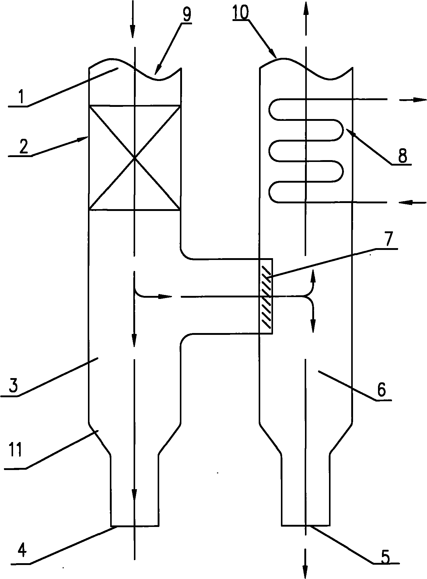
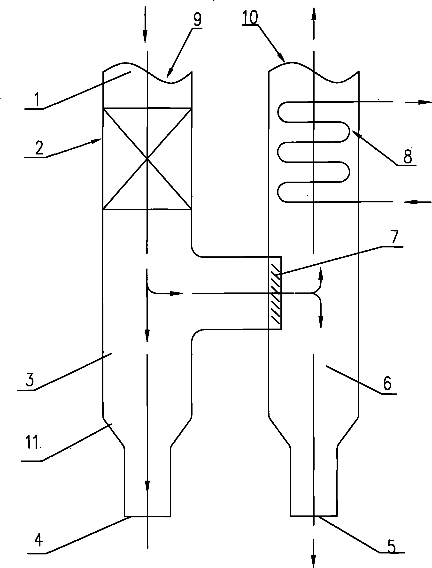
[0015] A waste heat recovery device, which includes a primary ash settling chamber 3 communicated with the flue 1, a secondary ash settling chamber 6 communicated with the primary ash settling chamber 3, and arranged in the primary ash settling chamber 6 The pre-evaporator 2 in the settling chamber 3 and the superheater 8 arranged in the secondary ash settling chamber 6 . The first-level ash settling chamber 3 and the second-level ash settling chamber 6 are arranged side by side in an "H" shape, and the upper part of the first-level ash settling chamber 3 is provided with a flue gas inlet 9, and the first-level ash settling chamber 6 is arranged side by side. There is a primary ash out...


PUM


Abstract

The invention discloses a waste heat recovery device. The device comprises a pre-evaporator, a primary ash settlement room, a secondary ash settlement room and a superheater, wherein the pre-evaporator and the primary ash settlement room are communicated with a flue; the secondary ash settlement room is communicated with the primary ash settlement room; the superheater is arranged in the secondary ash settlement room; the upper part of the primary ash settlement room is provided with a flue gas inlet; the lower part of the primary ash settlement room is provided with a primary ash discharge hole; the upper part of the secondary ash settlement room is provided with a flue gas outlet; the lower part of the secondary ash settlement room is provided with a secondary ash discharge hole; the superheater is arranged at the flue gas outlet; and an ash separator used for reducing a gas flow speed and separating ash is arranged between the primary ash settlement room and the secondary ash settlement room. The waste heat recovery device can separate ash from the flue gas very well, stabilize the temperature of the flue gas, and uniformize and stabilize a gas passing through the surface of the superheater so as to reduce local erosive wear of a heating surface of the superheater caused by the flue gas and avoid the explosion of a pipe.

Description

technical field [0001] The invention relates to a device for recovering waste heat or waste heat in chemical production, in particular to a waste heat recovery device for a sulfuric acid plant. Background technique [0002] A large amount of heat energy is generated during the production of sulfuric acid, and the grade of heat energy can be recycled from high to low. The best way to use high-grade heat energy is to generate electricity, which can greatly reduce production costs. In order to fully and efficiently recover the heat of reaction in each stage of the sulfuric acid production process, a superheater is usually installed in the waste heat recovery system of the sulfuric acid production equipment. The inside of the superheater is filled with saturated steam. Steam is used for turbo generator needs. Since the high-temperature flue gas produced in the acid production process contains a large amount of dust particles, when the high-temperature flue gas with a large ash ...

Claims


Application Information

Patent Timeline
Patent Type & Authority Applications(China)
IPC IPC(8): F27D17/00
CPCY02P80/15
Inventor 张宏
Owner JIANGNAN BOILERS & PRESSURE VESSELS ZHANGJIAGANG
Why Eureka
Try Eureka