Magnetic levitation linear guide rail of differential parallel magnetic circuit structure

A linear guide rail and magnetic levitation technology, applied in the direction of power rails, magnetic attraction or thrust holding devices, electrical components, etc., can solve the problems of large volume and weight, large ampere-turns of electric excitation, etc., and achieve small volume, loss and The effect of low temperature rise and light weight

Active Publication Date: 2011-02-09
HARBIN INST OF TECH
View PDF5 Cites 1 Cited by
  • Summary
  • Abstract
  • Description
  • Claims
  • Application Information

AI Technical Summary

Problems solved by technology

[0005] The purpose of the present invention is to solve the problem of large volume and weight of the existing magnetic levitation linear guide due to the large ampere-turns of the electric excitation, and to provide a differential parallel magnetic circuit structure magnetic levitation linear guide

Method used


Image

  • Magnetic levitation linear guide rail of differential parallel magnetic circuit structure
  • Magnetic levitation linear guide rail of differential parallel magnetic circuit structure
  • Magnetic levitation linear guide rail of differential parallel magnetic circuit structure

Examples


specific Embodiment approach 1

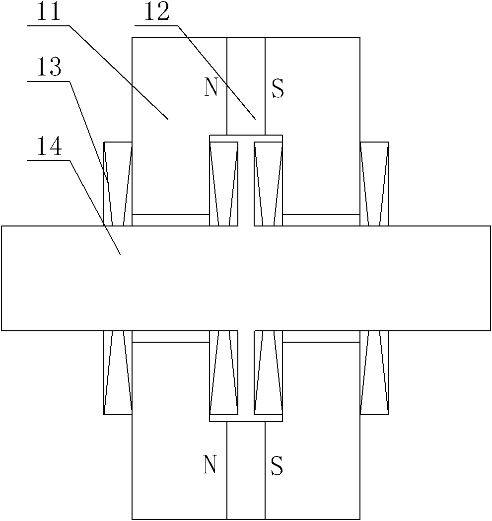
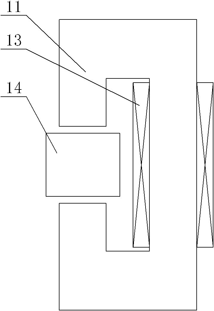
[0024] Specific implementation mode one: the following combination figure 1 and figure 2 Describe this embodiment, the differential parallel magnetic circuit structure magnetic levitation linear guide described in this embodiment is composed of a primary and a secondary,

[0025] The primary is composed of n+1 iron cores 11, 2n planar permanent magnets 12 and n+1 control coils 13, wherein n is a positive integer,

[0026] n+1 iron cores 11 are arranged parallel to each other and arranged side by side. The cross section of each iron core 11 is in the shape of a right angle C. A control coil 13 is wound on the back side of each iron core 11. The winding of the control coil 13 on the adjacent iron core 11 is To the contrary, all control coils 13 of the primary are connected in series,

[0027] The secondary includes a magnetically permeable yoke 14, the secondary is a long and narrow cuboid along the moving direction, and is located in the space formed by the C-shaped openings...

specific Embodiment approach 2

[0032] Embodiment 2: This embodiment is a further description of Embodiment 1. The magnetic yoke 14 is made of alloy steel, silicon steel sheet or SMC material. Other components and connections are the same as those in Embodiment 1.

[0033] In this embodiment, the magnetic yoke 14 is made of magnetic material.

specific Embodiment approach 3

[0034] Embodiment 3: This embodiment is a further description of Embodiment 1 or 2. The flat permanent magnet 12 is made of rare earth permanent magnet material. Other compositions and connections are the same as those in the first or second embodiment.

[0035] In this embodiment, the flat permanent magnet 12 is made of rare earth permanent magnet material, and the high performance of the rare earth permanent magnet material can be used to further reduce the ampere-turns of electric excitation.


PUM


Abstract

The invention discloses a magnetic levitation linear guide rail of a differential parallel magnetic circuit structure, which belongs to the technical field of motors and solves the problems of large volume and heavy weight caused by more ampere turns of electric excitation of the conventional magnetic levitation linear guide rail. In the first scheme, a control coil is wound on the back of each iron core, all control coils are connected in series, n+1 iron cores are mutually arranged in parallel, a secondary winding is positioned in a C-shaped open space of all the iron cores, and two flat permanent magnets are fixed between the adjacent two iron cores and positioned above and below the secondary winding respectively; and in the second scheme, each iron core consists of C-shaped magnetic conducting yokes and three iron core poles, the openings of the two C-shaped magnetic conducting yokes are opposite, a flat permanent magnet is fixed between the corresponding end faces of the C-shaped magnetic conducting yokes respectively, each C-shaped magnetic conducting yoke is provided with two vertical straight-tooth iron core poles and a horizontal straight-tooth iron core pole, a control coil is wound on each iron core pole, and a secondary winding is arranged in the center of an opening formed by a primary winding. The invention is applied in the magnetic levitation linear guide rail.

Description

technical field [0001] The invention relates to a differential parallel magnetic circuit structure magnetic levitation linear guide rail, which belongs to the technical field of motors. Background technique [0002] At present, the support methods of linear motion bodies mainly include linear sliding bearings, linear rolling bearings, linear guide rails and linear air bearings, among which linear sliding bearings and linear rolling bearings are only suitable for supporting short-stroke moving bodies; Rail, linear motion guide rail, linear slide rail or linear rolling guide rail, it has the advantages of high positioning accuracy, strong bearing capacity, small wear, adaptable to high-speed motion, unlimited travel, easy assembly and interchangeability, etc., has become a variety of Indispensable and important functional components in machine tools, CNC machining centers, and precision electronic machinery; linear air bearing guides have the advantages of high speed, high pre...

Claims


Application Information

Patent Timeline
Patent Type & Authority Applications(China)
IPC IPC(8): B60M1/30H02N15/00
Inventor 寇宝泉张赫张鲁
Owner HARBIN INST OF TECH
Why Eureka
Try Eureka