Linear quenching heat exchanger inlet connecting piece and quenching heat exchanger thereof

A quenching heat exchanger and inlet connection technology, which is applied in the direction of heat exchanger shell, heat exchange equipment, lighting and heating equipment, etc., can solve the problem of corrosion cracking, inconvenient maintenance and repair, welding Low strength and other problems, to achieve the effect of easy maintenance and repair, simple structure and short residence time

Active Publication Date: 2011-02-16
CHINA PETROLEUM & CHEM CORP +1
View PDF8 Cites 9 Cited by
  • Summary
  • Abstract
  • Description
  • Claims
  • Application Information

AI Technical Summary

Problems solved by technology

The cooling medium connectors in the prior art usually adopt an oblate tube structure, which can well absorb the thermal expansion difference stress between the inner tube and the outer tube of the double-tube heat exchange element, but the oblate tube and the inner tube of the double-tube heat exchange element The welded joints of the pipe and the outer pipe are corner joints, the welding strength is not high, and it is greatly affected by manufacturing factors, especially the corner joints between the flat round pipe and the inner pipe are prone to corrosion and cracking, and the flat round pipe and multiple double sleeves The inner tube and outer tube of the tube heat exchange element are connected, which is inconvenient for maintenance and repair
Another cooling medium connector in the prior art adopts a double-wall tube-sheet connector structure. The double-wall tube-sheet connector is only connected to a set of double-tube heat exchange elements, and the welded joint is a butt joint, but its disadvantage is that the tube sheet The thickness is large, and the thermal expansion difference stress between the inner tube and the outer tube of the double-sleeved heat exchange element must be reduced by pre-stretching the inner tube, which is difficult to manufacture

Method used


Image

  • Linear quenching heat exchanger inlet connecting piece and quenching heat exchanger thereof
  • Linear quenching heat exchanger inlet connecting piece and quenching heat exchanger thereof
  • Linear quenching heat exchanger inlet connecting piece and quenching heat exchanger thereof

Examples


Embodiment Construction

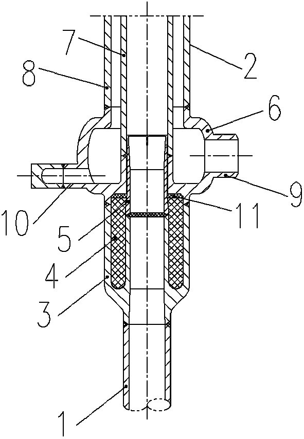
[0025] attached figure 1 It is a linear quenching heat exchanger inlet connector applying the present invention, and is only one form of the present invention, and the present invention is not limited thereto.

[0026] refer to figure 1 , one end of the inlet connector is butt welded with the cracking furnace outlet furnace tube 1, and the other end is butt welded with the double-tube heat exchange element 2. The high-temperature cracked gas enters the linear quenching heat exchanger from the furnace tube 1 at the outlet of the cracking furnace.

[0027] refer to figure 1 , The inlet connector consists of an inlet cone 3 , an insulator 4 , a seal 11 , a protective sleeve 5 and a cooling medium connector 6 . There is also an inwardly extending boss at the bottom of the cooling medium connecting piece 6, which is connected with the inner tube 7 of the double-tube heat exchange element 2, and the bottom inwardly extending boss and the top of the cooling medium connecting pi...


PUM


Abstract

The invention provides a linear quenching heat exchanger inlet connecting piece and a quenching heat exchanger thereof. The inlet connecting piece comprises an inlet cone (3), a heat insulating piece (4), a sealing piece (11), a protective sleeve (5) and a cooling medium connecting piece (6), wherein the cooling medium connecting piece (6) is a revolution body of which the cross section shape is a convex curve surface and can be used for better absorbing heat expansion difference stress between an inner pipe (7) and an outer pipe (8) of a double-sleeve heat exchanger element (2); and the protective sleeve (5) has good heat protection effect on a deep-hole welding head and the cooling medium connecting piece (6). The invention has the advantages of simple structure, long service life and short cracked gas retention time, and not only can be used for newly building a linear quenching heat exchanger of an ethylene cracking device, but also can be used for reforming a service linear quenching heat exchanger inlet connecting piece.

Description

technical field [0001] The invention relates to equipment used in ethylene cracking technology, in particular to an inlet connector of a linear quenching heat exchanger and the quenching heat exchanger thereof. Background technique [0002] The cracking furnace is the key unit of the ethylene plant. After the pyrolysis raw material undergoes high-temperature cracking in the cracking furnace tube, it enters the quenching heat exchanger for rapid cooling to prevent the occurrence of secondary reactions, reduce the loss of olefins, and at the same time recover heat energy to generate steam. With the development of quenching technology for ethylene cracking furnaces, in order to further shorten the residence time of the adiabatic section of the quenching heat exchanger and avoid the problem of uneven distribution of cracked gas, most of the quenching heat exchangers for newly built and renovated cracking furnaces currently use linear quenching heat exchangers. [0003] As we al...

Claims


Application Information

Patent Timeline
IPC IPC(8): F28F9/26F22B1/18
Inventor 李金科张建徐红兵康翼安发亮张贤福刘韫砚孙建兵毛小亮
Owner CHINA PETROLEUM & CHEM CORP
Why Eureka
Try Eureka