Eureka AIR delivers breakthrough ideas for toughest innovation challenges, trusted by R&D personnel around the world.

In-situ monitoring method for flux of methane gas on water-air interface

A methane gas and atmospheric technology, applied in the direction of measuring devices, suspension and porous material analysis, instruments, etc., can solve the problems of seldom considering the instantaneous temperature and pressure of sampling, difficult to achieve real-time monitoring, complicated operation, etc., to avoid light interference , simple structure and accurate measurement results

Inactive Publication Date: 2011-02-16
北京市华云分析仪器研究所有限公司
View PDF1 Cites 30 Cited by
  • Summary
  • Abstract
  • Description
  • Claims
  • Application Information

AI Technical Summary

Problems solved by technology

The existing water body-atmosphere methane gas flux measurement methods are basically replaced by gas box collection, remote sample delivery, and gas-intake gas chromatography (Document 2: Chen Yufen et al., 1996, Measuring rice field methane emissions by gas chromatography Fluxes, Environmental Science Research, (4): 21-24; Document 3: Tongchuan et al., 2008, Methane fluxes and influencing factors of Spartina alterniflora, an invasive species of Spartina alterniflora, in wet-mouthed Minjiang rivers, Geographical Sciences, 28(6) : 826-832), but the above-mentioned devices and methods have the problems of indirection, complicated operation and high cost, and rarely consider the temperature and air pressure at the instant of sampling, so it is difficult to achieve the purpose of real-time monitoring
At present, there are no reports on the methods and devices specially used to observe the water body-atmosphere methane gas flux

Method used


Image

  • In-situ monitoring method for flux of methane gas on water-air interface
  • In-situ monitoring method for flux of methane gas on water-air interface
  • In-situ monitoring method for flux of methane gas on water-air interface

Examples


Embodiment Construction

[0020] The present invention will be described in detail below in conjunction with the accompanying drawings and embodiments.

[0021] The inventive method comprises the following steps:

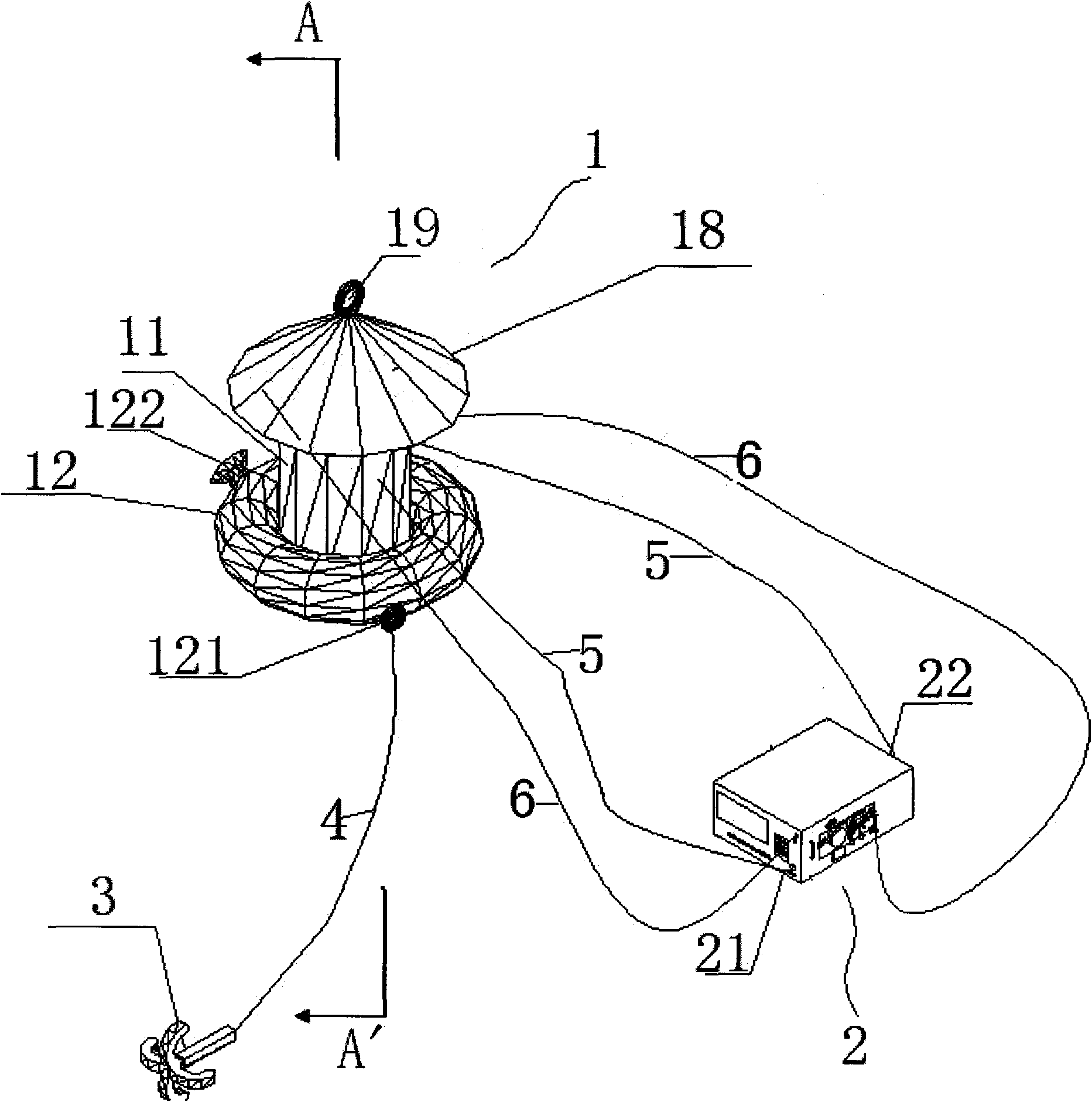
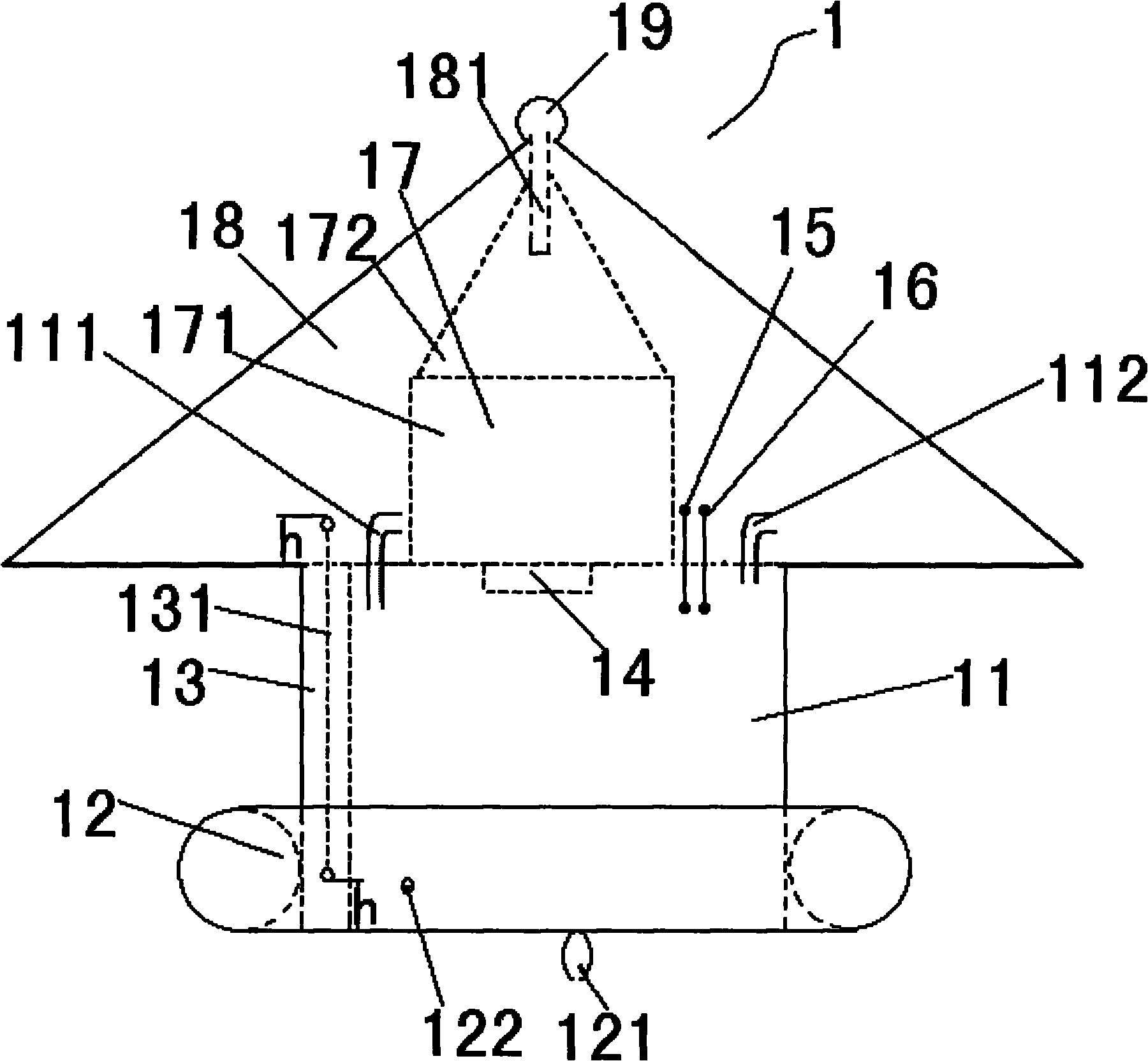
[0022] 1) Install a ring-shaped air bag at the opening of a box with an open bottom, connect the air bag to an anchor through a rope, and fill the air bag with air.

[0023] 2) Throw the anchor to the observation point, and after the box is stable, connect the gas in the box to the methane concentration measuring instrument through the air pipe.

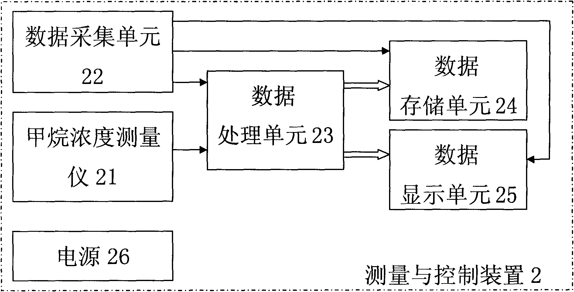
[0024] 3) Turn on the methane concentration measuring instrument, measure and record the methane gas concentration X1 at the water body-atmosphere interface, and record the measurement time t1.

[0025] 4) Measure and record the water level h in the tank and the actual height H of the tank in step 1).

[0026] 5) At the end of sampling, measure and record the methane gas concentration X2, temperature T2 and gas pressure P2 at the water body-atmos...


PUM


Abstract

The invention relates to an in-situ monitoring method for the flux of methane gas on a water-gas interface, which comprises the following steps of: 1) arranging a circular gasbag at the open of a tank with an open bottom, connecting the gasbag to an anchor through a rope, and filling gas in the gasbag; 2) throwing the anchor to an observation point, and after the tank is stabilized, connecting gas in the tank with a methane concentration measurement instrument through a gas tube; 3) starting the methane concentration measurement instrument, measuring and recording the methane gas concentration X1 on the water-gas interface, and recording the measurement time t1; 4) measuring and recording a water level h in the tank in the step 1) and an actual height H of the tank; 5) after the sampling is finished, measuring and recording the methane gas concentration X2, the temperature T2 and the gas pressure P2 on the water-gas interface, and recording the measurement time t2; and 6) calculating the flux of the methane gas between the water and the air by utilizing the methane gas concentration X1 and X2, the time t1 and t2, the water level h in the tank, the actual height H of the tank, the temperature T2 and the gas pressure P2 recorded in the steps 3), 4) and 5). The in-situ monitoring method is suitable for monitoring the flux of the methane gas between the water which takes paddy field, wetland, marshland, lake surface, river, sea, sewage and the like as an underlying surface and the air.

Description

technical field [0001] The invention relates to a method for measuring gas flux, in particular to an in-situ monitoring method for methane gas flux at the water body-atmosphere interface. Background technique [0002] Methane is one of the major greenhouse gases and is a long-lived greenhouse gas. The radiative forcing value of methane and its contribution to global climate change and impact are second only to carbon dioxide, and the scale involves the global space range, which has attracted widespread attention in recent years (Document 1: IPCC, 2007, Climate Change 2007: the physical science basis, World Environment , 13-22). In order to improve people's understanding of greenhouse gases and cope with global climate change, it is necessary to estimate and evaluate methane gas fluxes at global and regional scales, and to conduct scientific estimates and evaluations, field observations of methane gas fluxes must be carried out first. The existing water body-atmosphere meth...

Claims


Application Information

Patent Timeline
Patent Type & Authority Applications(China)
IPC IPC(8): G01N15/06G01N33/00G01N1/22
Inventor 高程达唐青云
Owner 北京市华云分析仪器研究所有限公司
Why Eureka
Eureka Blog
Learn More