Liquid crystal driving device and sequential control circuit and method for improving startup delay

A timing control circuit, liquid crystal driving technology, applied in the direction of instruments, static indicators, etc., can solve problems such as boot delay, increased charging time of node N1, and voltage that cannot meet demand

Active Publication Date: 2011-02-16
苏州盛泽科技创业园发展有限公司
View PDF4 Cites 2 Cited by
  • Summary
  • Abstract
  • Description
  • Claims
  • Application Information

AI Technical Summary

Problems solved by technology

In this way, the parasitic capacitance of the thin film transistor T2 also increases, causing the charging time of the node N1 to increase
Therefore, the voltage of node N1 at the initial stage of starting up will not be able to meet the demand, resulting in a delay in starting up

Method used


Image

  • Liquid crystal driving device and sequential control circuit and method for improving startup delay
  • Liquid crystal driving device and sequential control circuit and method for improving startup delay
  • Liquid crystal driving device and sequential control circuit and method for improving startup delay

Examples


Embodiment Construction

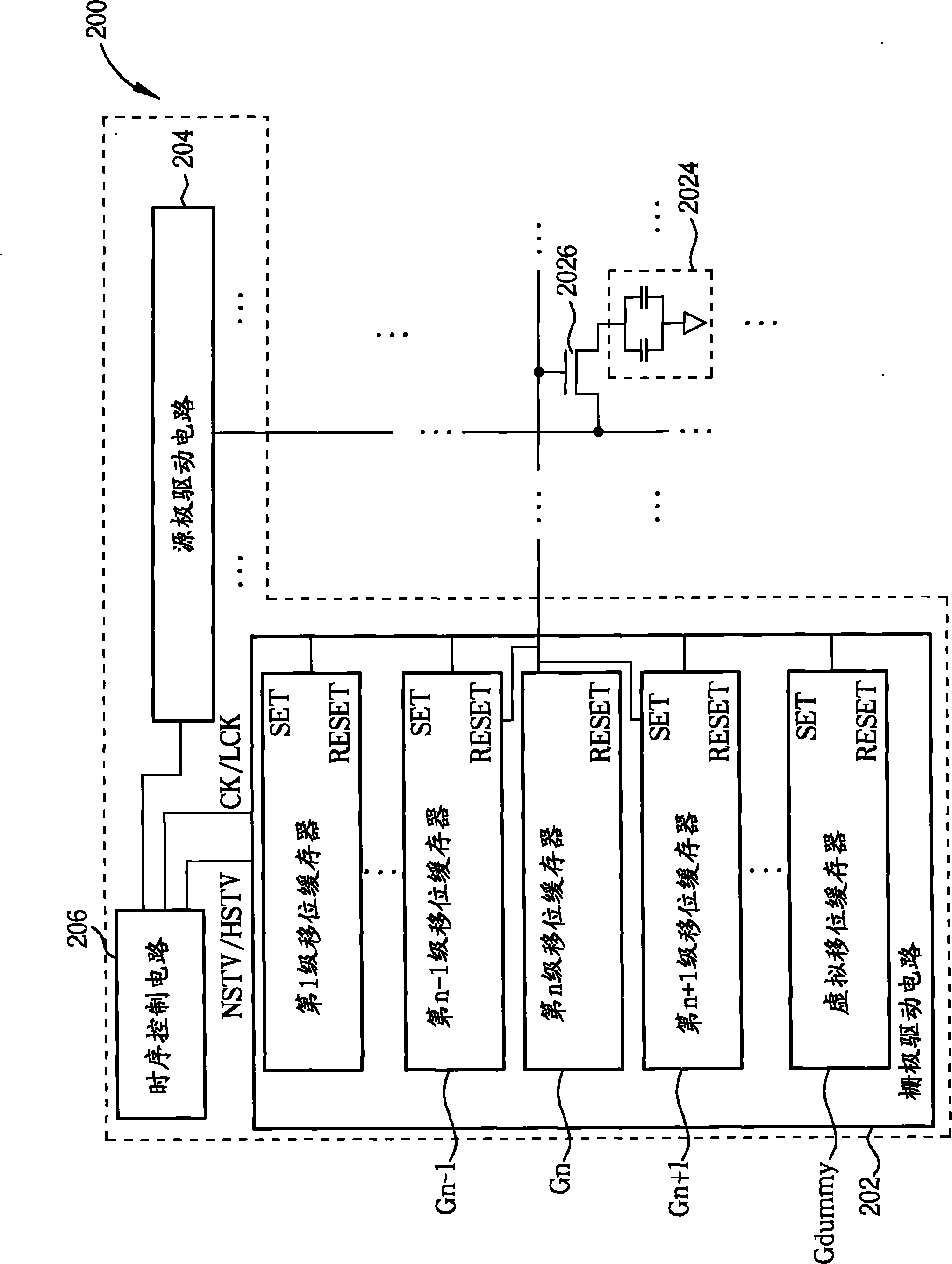
[0014] Please refer to figure 2 , figure 2 It is a schematic diagram illustrating a liquid crystal driving device 200 for improving power-on delay according to an embodiment of the present invention. The liquid crystal driving device 200 includes a gate driving circuit 202 , a source driving circuit 204 and a timing control circuit 206 . The gate driving circuit 202 includes a plurality of shift registers, and the plurality of shift registers are connected to each other by coupling output terminals. For example, the plurality of shift registers includes an n-1th stage shift register Gn-1, an nth stage shift register Gn, and an n+1th stage shift register coupled in sequence device Gn+1, wherein the signal at the output end of the shift register Gn of the nth stage is used as the input signal of the setting terminal SET of the shift register Gn+1 of the n+1 stage and the shift register of the n-1 stage It is worth noting that the signal at the output end of the dummy shift ...


PUM


Abstract

The invention relates to a liquid crystal driving device and sequential control circuit and method for improving startup delay, wherein the liquid crystal driving device comprises a grid driving circuit, a source driving circuit and a sequential control circuit, wherein the sequential control circuit is coupled to the grid driving circuit and is used for sending out a low-frequency frame frequency which is lower than the normal frame frequency of a liquid crystal display and a high-frequency scanning start signal the frequency of which is higher than the that of the normal scanning start signal of the liquid crystal display when the liquid crystal display is started up to operate a preset frequency number of the grid driving circuit, and then, the low-frequency frame frequency is modulated to the normal frame frequency of the liquid crystal display and the high-frequency scanning start signal is modulated to the normal scanning start signal of the liquid crystal according to the trigger signal of the sequential control circuit; and the liquid crystal display is operated according to the normal frame frequency and the normal scanning start signal.

Description

technical field [0001] The present invention relates to a liquid crystal driving device and its method, especially to a liquid crystal driving device and its method which can improve the startup delay. Background technique [0002] Please refer to figure 1 , figure 1 is a schematic diagram illustrating a shift register 100 applied in a gate driving circuit. Such as figure 1 As shown, when the scan start signal of the liquid crystal display is at a high potential (the liquid crystal display is turned on), the scan start signal is input to the input terminal IN1 of the shift register 100 in the gate drive circuit, and the thin film transistor T1 is turned on at this time, As a result, the node N1 starts charging and the thin film transistor T2 turns on. However, since the frame frequency CK input from the input terminal CK1 is at a low potential at this time, the output signal at the output terminal OUT of the shift register 100 (potential at the source terminal of the thi...

Claims


Application Information

Patent Timeline
Patent Type & Authority Applications(China)
IPC IPC(8): G09G3/20G09G3/36
Inventor 黎鸿俊蓝东鑫王俊杰
Owner 苏州盛泽科技创业园发展有限公司
Why Eureka
Try Eureka