High-efficiency power regulating device based on power factor correction

A technology of power factor correction and power regulation, which is applied in the direction of output power conversion device, AC power input conversion to AC power output, high-efficiency power electronic conversion, etc. high weight problem

Inactive Publication Date: 2011-02-16
UNIV OF ELECTRONIC SCI & TECH OF CHINA
View PDF3 Cites 14 Cited by
  • Summary
  • Abstract
  • Description
  • Claims
  • Application Information

AI Technical Summary

Problems solved by technology

[0003] The traditional power adjustment device has some obvious defects, such as high harmonic components (such as phase-shift power adjustment), low power factor (such as saturated reactor power adjustment), which make it unable to meet the requirements of energy saving and environmental protection
The power factor correction (PFC) t

Method used


Image

  • High-efficiency power regulating device based on power factor correction
  • High-efficiency power regulating device based on power factor correction
  • High-efficiency power regulating device based on power factor correction

Examples


Embodiment

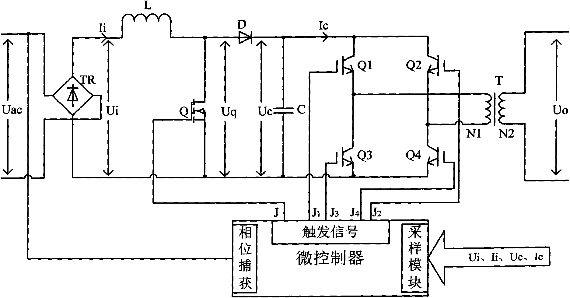
[0040] figure 1 It is a schematic diagram of a specific implementation of a high-efficiency power adjustment device based on power factor correction.

[0041] Such as figure 1 As shown, in this embodiment, the high-efficiency power regulation device based on power factor correction of the present invention includes a front-end power factor correction circuit, a back-end power adjustment circuit and a microcontroller.

[0042] The front-end power factor correction circuit includes a full-bridge rectifier circuit TR, an energy storage inductor L, a metal oxide semiconductor field effect transistor (hereinafter referred to as MOSFET) Q, a diode D and an energy storage capacitor C. The sinusoidal voltage Uac obtained from the power grid passes through the full-bridge rectifier circuit TR to output a DC voltage Ui, and then transmits it to the positive terminal of the diode D through the energy storage inductor L, and then outputs it to the positive terminal of the energy storage ...


PUM


Abstract

The invention discloses a high-efficiency power regulating device based on power factor correction, which comprises a front-end power factor correction circuit, a back-end power regulating circuit and a microcontroller. A phase trapping module is used for trapping the zero crossing point (ZCP) of sine voltage Uac acquired from an electric network, and a sampling module is used for acquiring rectified DC voltage Ui, current Ii, voltage Uc at two ends of an energy storage capacitor and output current Ic when insulated gate bipolar transistors Q1 and Q4 or Q2 and Q3 are conducted; then, a pulse triggering signal J is output to control the on-off of a metal oxide semiconductor field effect transistor (MOSFET) in the front-end power factor correction circuit, pulse triggering signals J1 and J4 are respectively output to the insulated gate bipolar transistors Q1 and Q4, and pulse triggering signals J2 and J3 of which the time sequence is 1/2Tc delayed than the time sequence of the pulse triggering signals J1 and J4 and the duty ratio is the same as the duty ratio of the pulse triggering signals J1 and J4 are respectively output to the insulated gate bipolar transistors Q2 and Q3 to control the on-off of the insulated gate bipolar transistors Q1, Q2, Q3 and Q4; and finally, the high-efficiency power regulating device outputs larger power required by the load and simultaneously ensures that the power factor is approximate to 1 and the harmonic component is very low.

Description

technical field [0001] The invention belongs to the technical field of power adjustment, and more specifically relates to a high-efficiency power adjustment device based on power factor correction. Background technique [0002] Today, when energy conservation and environmental protection attract much attention, electricity, as a clean and convenient energy source, has been more and more widely used. However, this does not mean that as long as it is driven by electricity, it will be energy-saving and environmentally friendly. Factors such as whether the electrical equipment itself has an ideal power factor and whether it will cause pollution to the power grid have a decisive impact on the realization of this goal. Therefore, to save energy and protect the environment, we must It is necessary to ensure that the electrical equipment has the characteristics of grid friendliness. Because some characteristics of the electrical equipment itself are difficult to change, it is the m...

Claims


Application Information

Patent Timeline
IPC IPC(8): H02M1/42H02M5/458
CPCY02B70/126Y02B70/10
Inventor 程玉华白利兵周科陈凯
Owner UNIV OF ELECTRONIC SCI & TECH OF CHINA
Why Eureka
Try Eureka