
Permanent magnet rotor with flux concentrating pole pieces

A technology of permanent magnets and rotors, applied in the direction of magnetic circuit rotating parts, magnetic circuits, magnetic circuit shape/style/structure, etc., can solve the problems of increasing rotor weight and inertia moment, etc., to improve performance, reduce costs, and reduce production cost effect

Inactive Publication Date: 2011-02-16
HOGANAS AB
View PDF6 Cites 8 Cited by
  • Summary
  • Abstract
  • Description
  • Claims
  • Application Information

AI Technical Summary

Problems solved by technology

The currently known method of arranging low-performance magnets is to enlarge the rotor in the entire radial direction, which will increase the weight and moment of inertia of the rotor

Method used


Image

  • Permanent magnet rotor with flux concentrating pole pieces
  • Permanent magnet rotor with flux concentrating pole pieces
  • Permanent magnet rotor with flux concentrating pole pieces

Examples


Embodiment Construction

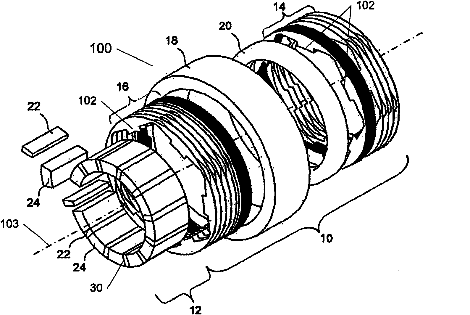
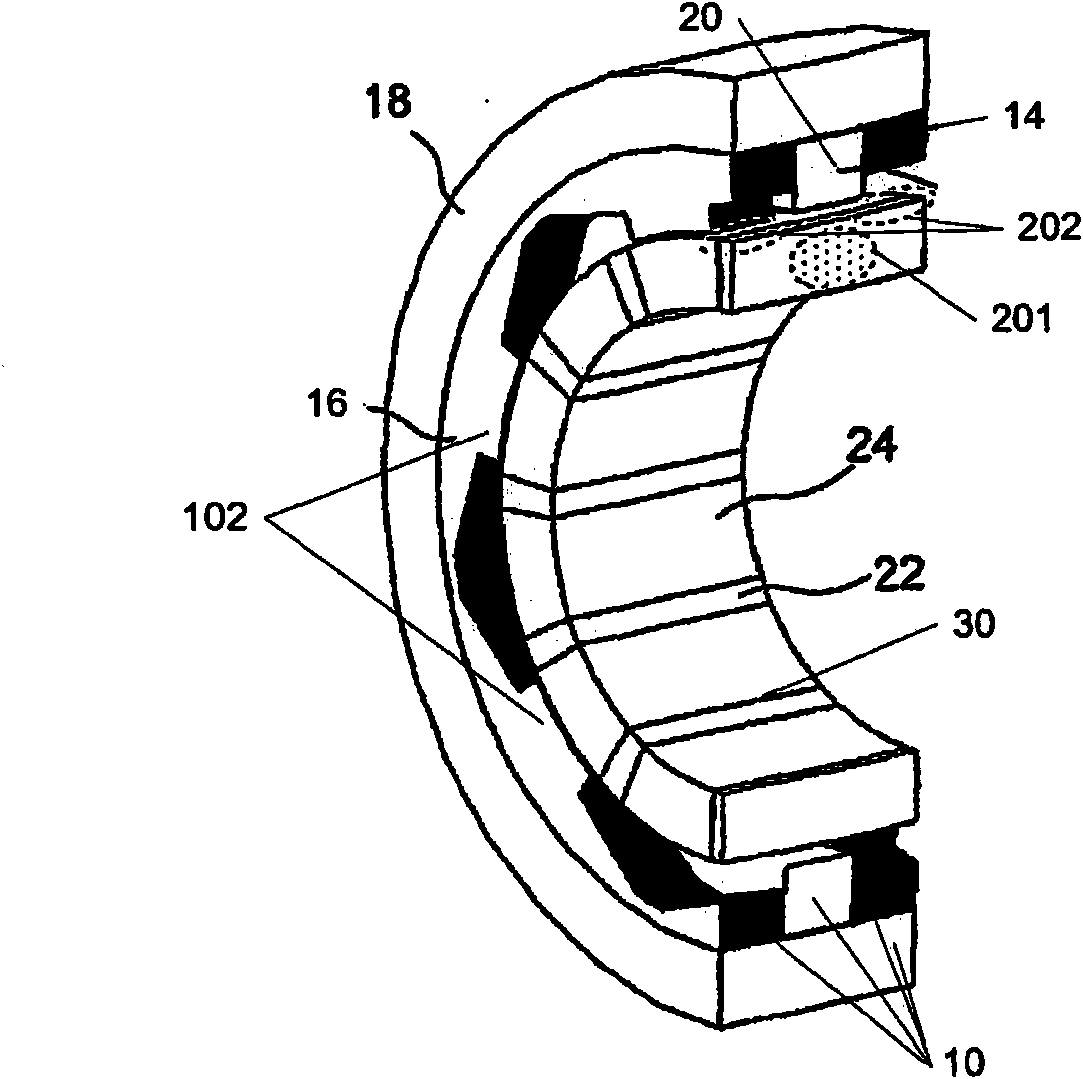
[0031] The present invention is in the field of permanent magnet electric machines 100 , an example of which is shown in the exploded perspective schematic diagram of FIG. 1 . A fundamental feature of the permanent magnet motor stator 10 is the use of a magnetic coil, eg, a central single winding 20, which provides magnetism to a plurality of teeth 102 formed from a soft magnetic core structure. The stator core is then formed around the windings 20, although in other common electric machine constructions the windings are formed around the individual tooth core segments. Examples of modulated pole machine layouts are sometimes considered to include, for example, claw pole, hook foot, Rendell or TFM machines. More specifically, a permanent magnet electric machine 100 is shown comprising: two stator core sections 14 and 16 each comprising a plurality of teeth 102 and having a substantially annular shape; disposed between first and second annular stator core sections a coil 20; a...


PUM


Abstract

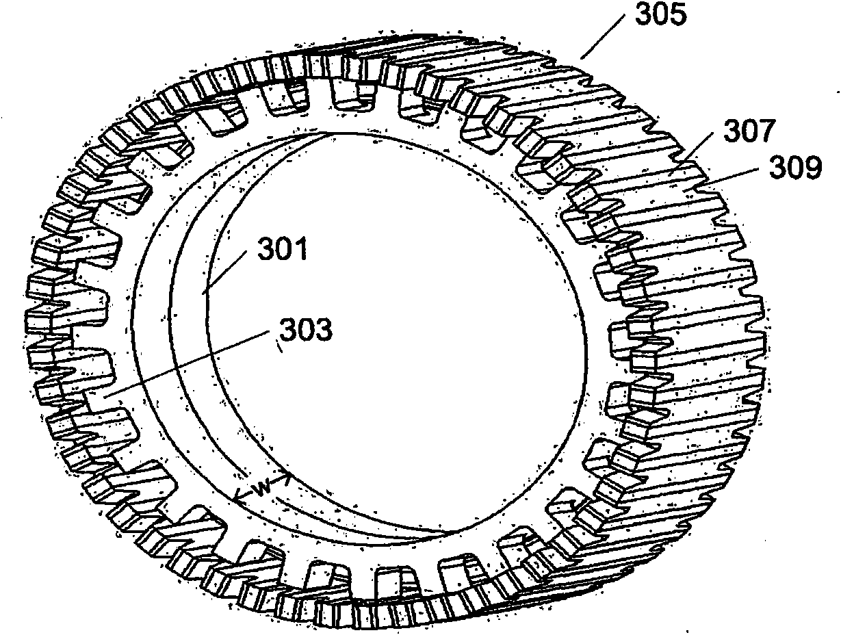
The present invention relates to a permanent magnet machine comprising a stator (301) and a rotor (305), the rotor (305) being adapted to rotate relative to the stator (301), the rotor (305) comprising a plurality of permanent magnets (307) separated in the circumferential direction from each other by axial Iy extending rotor pole pieces (309) for concentrating the magnetic flux from said permanent magnets (307), the stator (301) having a structure that defines axial limits of an air gap between the stator (301) and the rotor (305) for communicating magnetic flux between the stator (301) and the rotor (305), characterized in that at least some of the permanent magnets (307) extend axially outside the axial limits of the air gap as defined by the stator structure.

Description

technical field [0001] The invention relates to the field of permanent magnet motors, in particular to a DC brushless permanent magnet motor. Background technique [0002] Permanent magnet motors, especially DC brushless permanent magnet motors, can be realized as electrically modulated pole motors. In recent years, motor designs gradually developed from modulated pole motors, claw pole motors, Lundell motors and transverse field motors (TFM) have attracted more and more attention. As early as about 1910, Alexandersson and Fessenden proposed a motor using the above motor principle. One of the most important reasons for this growing interest is that the design enables extremely high torque outputs compared to, for example, induction motors, switched reluctance motors, or even permanent magnet brushless motors. In addition, the advantage of this type of motor is that its coils are usually easy to manufacture. Examples of implementations of modulated pole motor topologies in...

Claims


Application Information

Patent Timeline
IPC IPC(8): H02K1/27
CPCH02K1/2793H02K1/2786H02K1/2791
Inventor L-O·彭纳德A·G·杰克G·J·阿特金森
Owner HOGANAS AB
Learn More