
Spray drying tower for preparing powder

A spray drying tower and tower body technology, which is applied in the direction of drying solid materials, drying gas arrangement, drying, etc., can solve the problems of high damage rate, large product deformation, and reduced pressing efficiency, so as to improve pressing forming efficiency and reduce The effect of planing and grinding and reducing the shrinkage of firing

Active Publication Date: 2011-02-23
佛山市科达机电有限公司
View PDF8 Cites 14 Cited by
  • Summary
  • Abstract
  • Description
  • Claims
  • Application Information

AI Technical Summary

Problems solved by technology

[0004] 1. The temperature of the incoming air is high, and it is difficult to use the waste hot air discharged from kilns and other related equipment;
[0005] 2. The powder particles expand and burst rapidly, producing a large amount of fine powder, which reduces the utilization rate of qualified powder particles made from mud;
[0006] 3. The dust content of exhaust gas emission is large, which increases the investment in dust removal equipment and the energy consumption of related equipment;
[0007] 4. The mud is transported by a single main pipe, and the particle gradation is difficult to control;
[0008] 5. The powder is a hollow body, and the exhaust volume is large during pressing, which reduces the pressing efficiency;
[0009] 6. The molding density of the green body is low, the strength is weak, and the damage rate in the transportation process is large;
[0010] 7. The shrinkage rate is large during the firing process, and the product deformation is large;
[0011] 8. Semi-finished products that must be planed and edging, the amount of planing and edging is relatively large

Method used


Image

  • Spray drying tower for preparing powder
  • Spray drying tower for preparing powder
  • Spray drying tower for preparing powder

Examples


Embodiment Construction

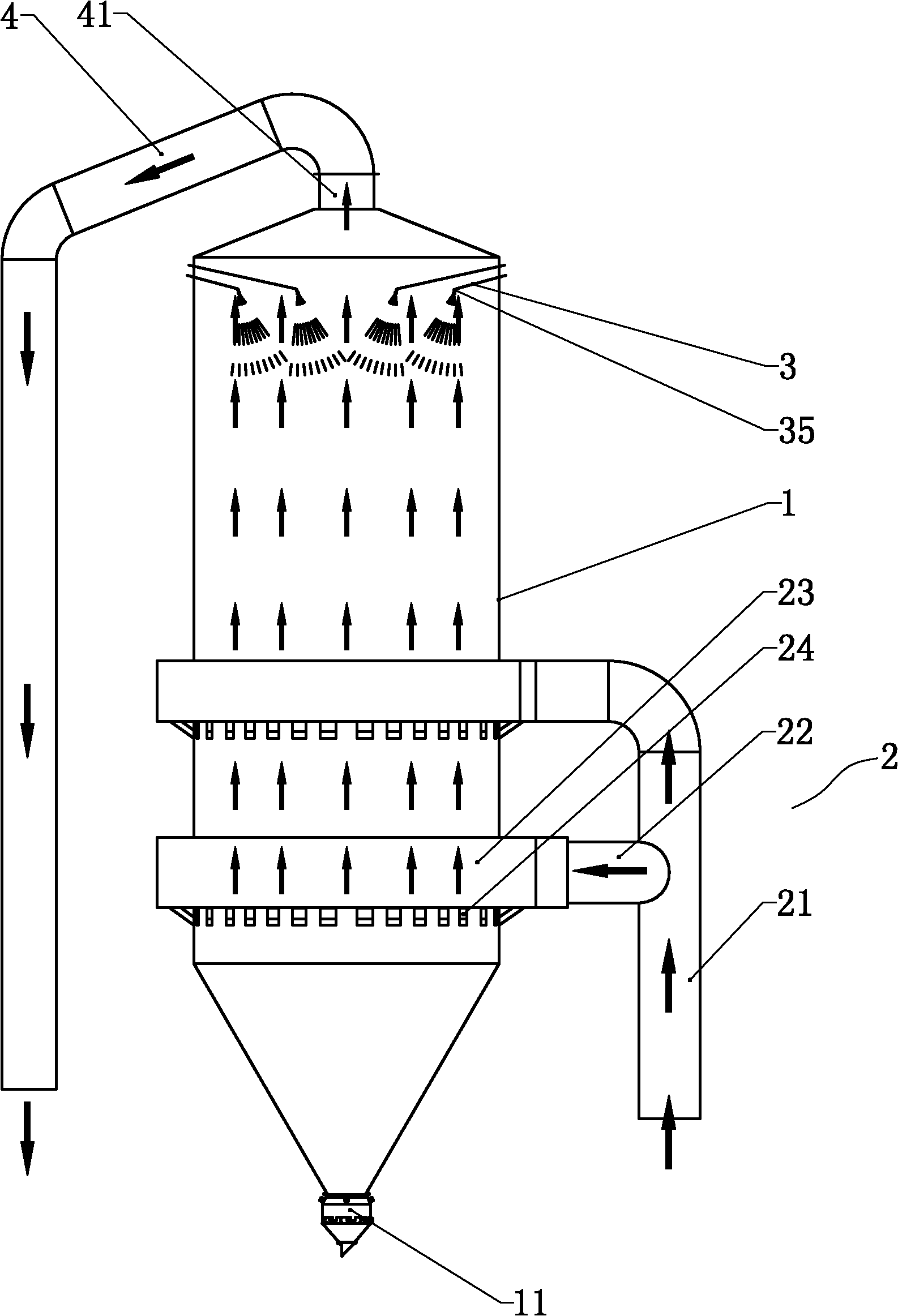
[0039] Such as figure 1 As shown, the spray drying tower for ceramic powder making according to the present invention includes a tower body 1, the bottom of the tower body 1 is provided with a powder outlet 11, and the top of the tower body is provided with an air outlet connected to the exhaust device 4 41. The tower body 1 is also provided with a hot air supply device 2 and a slurry supply atomization device 3 .

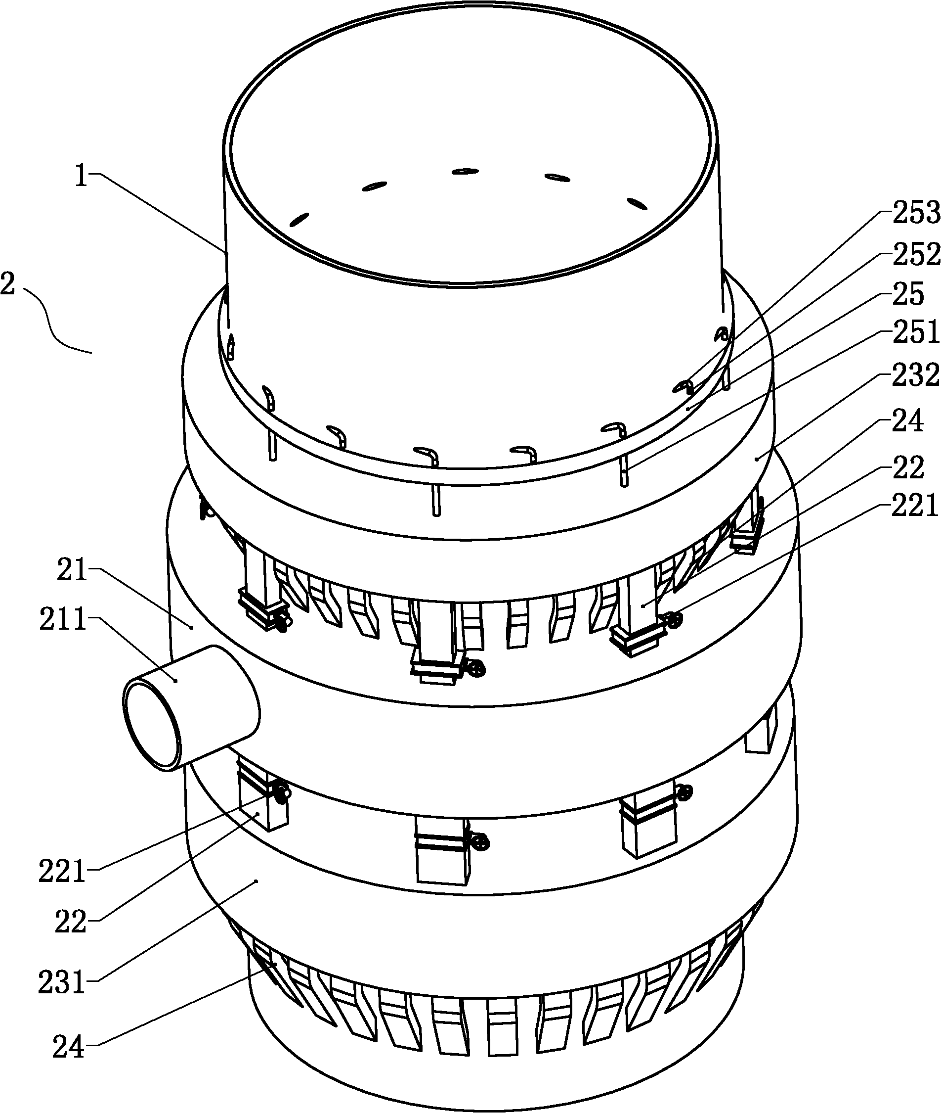
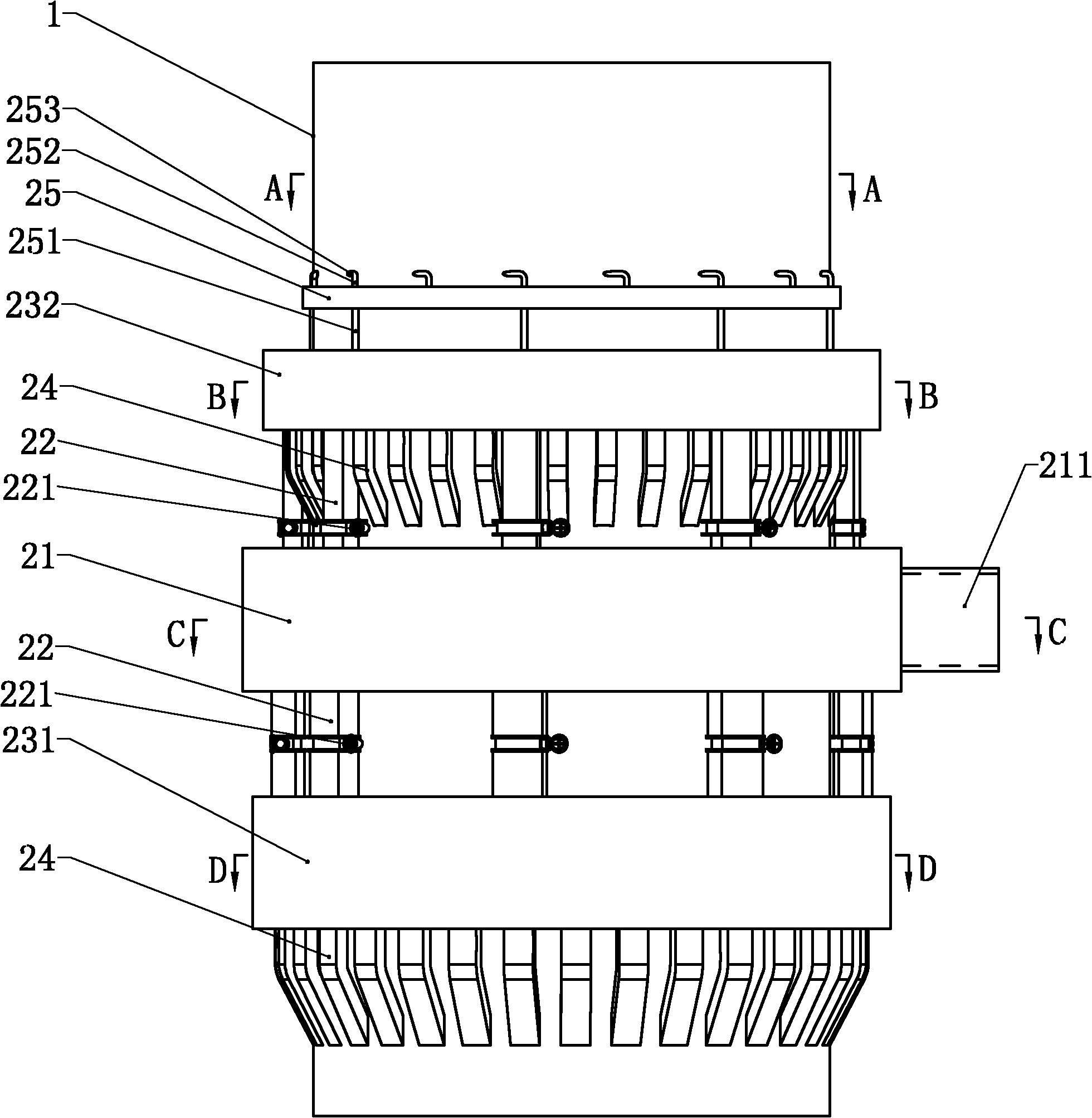
[0040] The hot air supply device 2 includes a balanced air pipe 21 and two hot air pipes 23. The balanced air pipe 21 is connected to the hot air source through a pipeline, and the two hot air pipes 23 are respectively arranged around the outer wall of the tower body 1 on the peripheral wall of the tower body. The middle part and the lower part, and communicate with the balance air pipe 21 through a regulating pipe 22 respectively. Corresponding to each hot-blast pipe 23 is provided with some hot-blast sub-pipes 24, one end of each hot-blast sub-pipe 24 communica...


PUM


Abstract

The invention belongs to the technical field of spray drying, and discloses a spray drying tower for preparing powder. The spray drying tower comprises a tower body, wherein the tower body is provided with a hot air supply device, an exhaust device and a slurry-feeding atomization device; the bottom of the tower body is provided with a powder outlet; a plurality of tower air inlets of the hot airsupply device are formed on the inside walls of the middle part and the lower part of the tower body, and the temperature of the tower inlet hot air is gradually reduced from bottom to top; and the exhaust port of the exhaust device is formed on the upper part of the tower body. Through counter flow type structural design, the slurry is first contacted with the low-temperature hot air in the tower and then contacted with medium-temperature and high-temperature hot air in turn to generate solid spherical powder so as to effectively solve and improve the technical problems of the prior art. Thespray drying tower can make full use of waste heat, reduce energy consumption and reduce emission; and the ceramic powder treated by the tower can achieve the technical effects of improving the pressing forming efficiency, increasing the strength of the blank, reducing sintering shrinkage, reducing planed edge polishing quantity and the like. The spray drying tower is also suitable for other spray drying powder preparation processes.

Description

technical field [0001] The invention belongs to the technical field of spray drying, and in particular relates to a spray drying tower for powder making. Background technique [0002] The powder obtained through the spray drying tower, such as ceramic powder, has the characteristics of fineness and stable moisture content, which ensures that the internal stress of ceramic products is relatively uniform. Therefore, the spray drying tower is one of the necessary equipment in the current ceramic production process. Its Performance directly affects the output and quality of powder, is related to energy consumption and environmental protection, and has a profound impact on the quality and cost of the final product. [0003] The existing spray drying towers for ceramic powder making are all mixed-flow type, and its structure is mainly to install a hot air device, an exhaust device, a slurry atomization device and a powder outlet on a tower body, and the inlet of the hot air device...

Claims


Application Information

Patent Timeline
IPC IPC(8): F26B17/10F26B21/12F26B25/00F26B21/00
Inventor 段高峰谢颖纯黄开兴
Owner 佛山市科达机电有限公司
Learn More