Motor controller, air compressor, air conditioner, controller of passenger conveyor and controller of conveyor

一种乘客输送装置、空气压缩机的技术,应用在电动机控制、单个电动机转速/转矩控制、控制装置等方向,能够解决电动机失去同步等问题,达到延长寿命的效果

Active Publication Date: 2011-03-02
HITACHI LTD
View PDF8 Cites 18 Cited by
  • Summary
  • Abstract
  • Description
  • Claims
  • Application Information

AI Technical Summary

Problems solved by technology

[0004] When you want to control the synchronous motor to drive the compressor, etc., and give a predetermined rotational speed as the control command value, you want to drive the synchronous motor according to the command value When , a larger torque (torque, torque) is generated, which may cause the motor to lose synchronization depending on the situation

Method used


Image

  • Motor controller, air compressor, air conditioner, controller of passenger conveyor and controller of conveyor
  • Motor controller, air compressor, air conditioner, controller of passenger conveyor and controller of conveyor
  • Motor controller, air compressor, air conditioner, controller of passenger conveyor and controller of conveyor

Examples


Embodiment 1

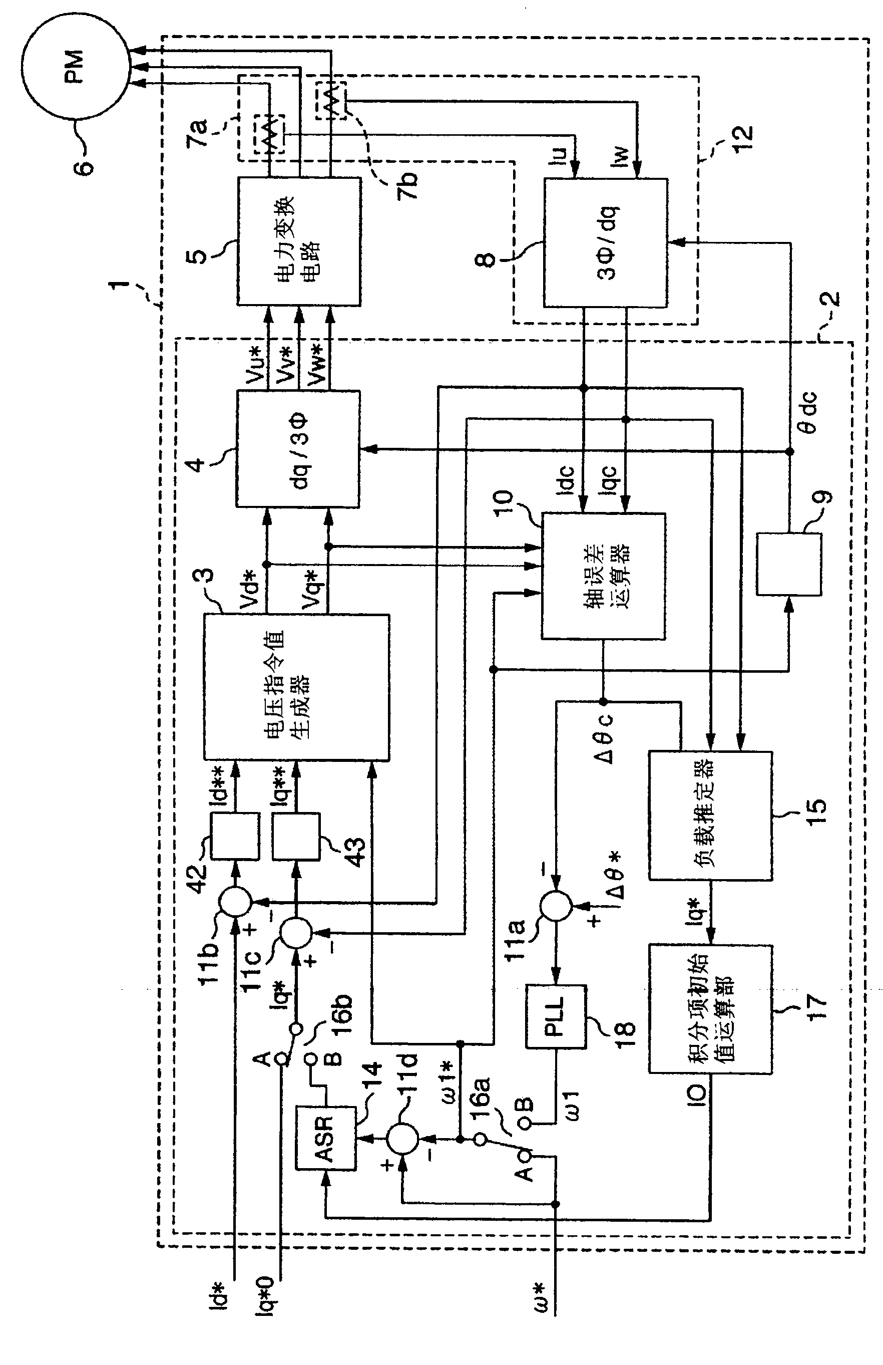
[0047] Embodiment 1 of the motor control device of the present invention will be described with reference to the drawings. figure 1 A configuration diagram showing an AC motor drive system that is an embodiment of the present invention.

[0048] This structural diagram includes a three-phase permanent magnet synchronous motor 6, a motor control unit 1 that controls the driving of the permanent magnet synchronous motor 6, and a power conversion circuit (power conversion circuit) 5 that drives the permanent magnet synchronous motor 6. In the motor control unit 1 Inside, the rotor position estimation calculation and speed control of the permanent magnet synchronous motor 6 are performed, that is, the control without (requiring) a position sensor is performed. In position sensorless control, since the position of the rotor cannot be judged when the motor is not rotating, it is not clear how the electric current can be started.

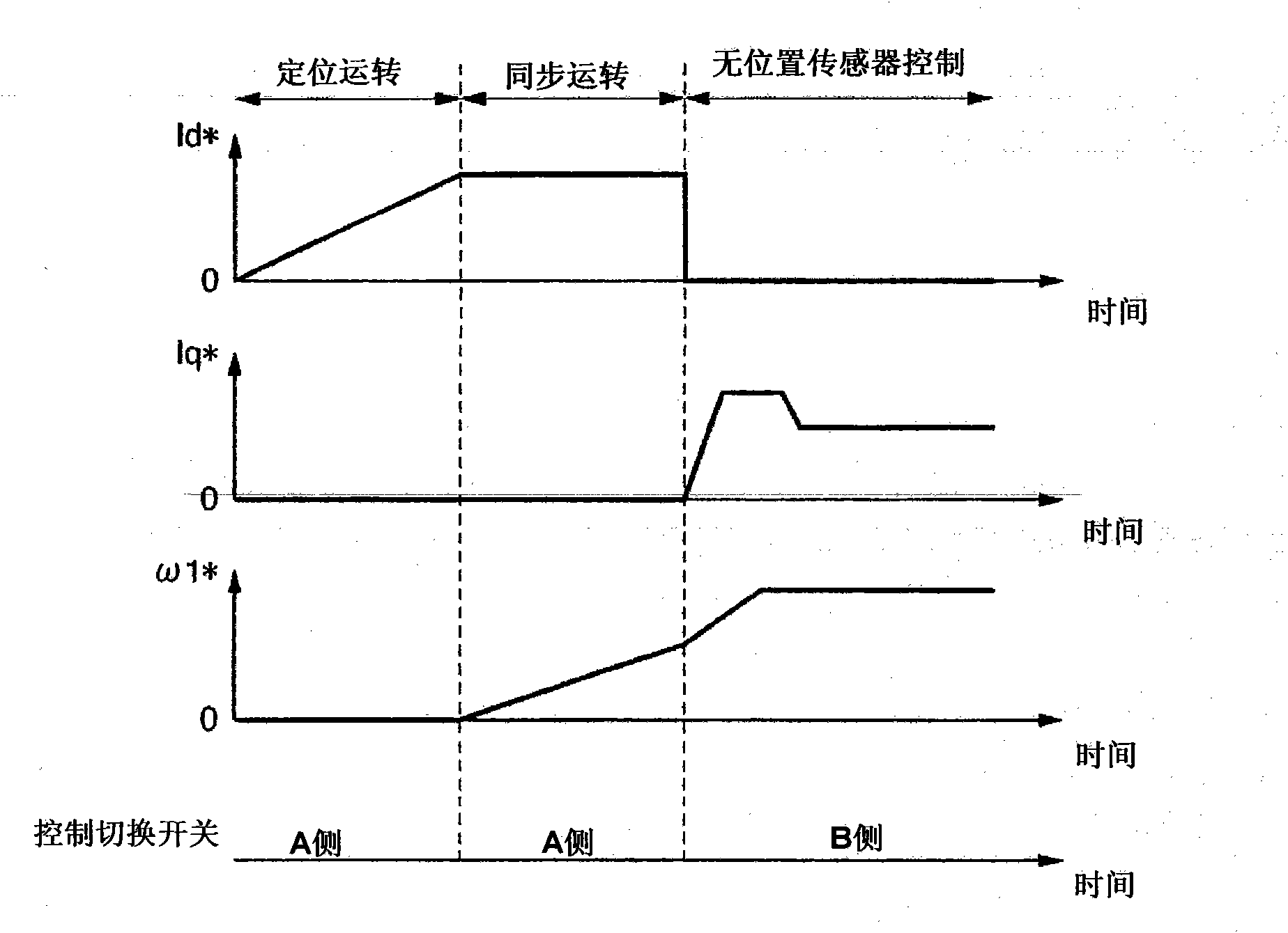
[0049] Therefore, in this embodiment, the permanent...

Embodiment 2

[0103] Embodiment 2 of the motor control device of the present invention will be described with reference to the drawings.

[0104] This embodiment is basically based on the same idea as that of Embodiment 1, reducing the starting current of the permanent magnet synchronous motor. That is, in Embodiment 1, the case where the permanent magnet synchronous motor was mounted on the air compressor was described, but the case where the permanent magnet synchronous motor is mounted on other products can also be started with the same idea.

[0105] Here, a case where a permanent magnet synchronous motor is mounted on an electric compressor used in an air conditioner, a refrigerator, or the like will be described. An electric compressor used in an air conditioner constitutes a so-called refrigeration cycle in which a refrigerant is circulated by rotating a permanent magnet synchronous motor. That is, heat is transferred by compressing or expanding refrigerant gas while circulating it....

Embodiment 3

[0116] Hereinafter, Embodiment 3 of the present invention will be described.

[0117] This embodiment utilizes the automatic stop function provided on the air compressor for energy saving. This automatic stop function will be described.

[0118] Such as Figure 4 As shown in the structural diagram of the air compressor, the air compressor is provided with a pressure sensor 105 that detects the pressure of the discharge to the discharge side of the compressor main body, and the output signal of the pressure sensor is sent to the input and output part 106, sent to to the air compressor control unit 101. Then, in the air compressor control unit 101, the detected value is compared with the preset target pressure, and the frequency at which the detected value can become the target pressure is given to the motor control unit 1. Correspondingly, the motor control unit 1 controls the permanent magnet synchronous The speed of the motor 6. As a result, the speed of the compressor ma...


PUM


Abstract

A motor controller for controlling a synchronous motor by feeding a current thereto is equipped with a receiving section for receiving the detection value of a temperature detector provided in the synchronous motor. When a synchronous motor is started, magnitude of a current being fed to the synchronous motor is varied depending on the temperature received at the receiving section in order to stabilize starting thus prolonging the lifetime of semiconductor elements.

Description

[0001] import by reference [0002] This application claims the priority of Japanese Patent Application No. 2008-089125 for which it applied on March 31, 2008, The content is taken in into this application by reference. technical field [0003] The present invention relates to the technology of motor control, in particular to the control technology for starting (starting) motors. Background technique [0004] When a synchronous motor is intended to be controlled to drive a compressor, etc., and a predetermined rotation speed is given as a control command value, and a synchronous motor is driven according to the command value, a large torque (torque, torque) is generated. According to Circumstances may cause the motor to lose synchronization. Japanese Patent Application Laid-Open No. 2003-28073 describes that, in a compressor having a piston that compresses a refrigerant, it is possible to discharge the liquefied refrigerant and perform stable startup. [0005] In addition,...

Claims


Application Information

Patent Timeline
Patent Type & Authority Applications(China)
IPC IPC(8): H02P6/20F04B49/06F04B49/02H02P6/06H02P6/08
CPCB60L2240/36H02P21/0039H02P29/0088H02P21/0032Y02B50/225Y02T10/642H02P21/34H02P21/24H02P29/68Y02T10/64B66B25/00F04C28/06
Inventor 大久保智文铃木宣长上松初田中英晴长谷征和田口义行
Owner HITACHI LTD
Why Eureka
Try Eureka