
Press roller device for vacuum rotary drum filter

A pressure roller device and filter technology, applied in the direction of filtration separation, moving filter element filter, separation method, etc., can solve the problems of shortening the service life of the pressure roller, reducing the working efficiency of the pressure roller, and poor corrosion resistance of the pressure roller body , to achieve strong corrosion resistance and wear resistance, reduce operation and maintenance costs, and smooth roll body rotation

Inactive Publication Date: 2011-03-16
CHENGDU TIANBAO HEAVY IND
View PDF12 Cites 2 Cited by
  • Summary
  • Abstract
  • Description
  • Claims
  • Application Information

AI Technical Summary

Problems solved by technology

The surface of the pressure roller (stainless steel or cast iron) of the traditional structure is very easy to stick to the wet filter cake, so it is necessary to add a scraper cleaning device to clean the filter cake on the surface of the pressure roller at any time, which increases the manufacturing cost and operation and maintenance workload
The cutting edge of the cleaning scraper is close to the working surface of the pressure roller for a long time, which causes serious wear on the working surface of the pressure roller, reduces the working efficiency of the pressure roller, and shortens the service life of the pressure roller; the unevenly worn scraper cannot be completely cleaned The bonded filter cake on the pressure roller causes the surface of the pressure roller to be uneven, which not only fails to smooth the filter cake, but also destroys the surface quality of the filter cake, and even causes a loss of vacuum degree; at the same time, the traditional structure of the pressure roller body has poor corrosion resistance and the pressure The service life of the roller body is short, and existing devices such as Figure 4 shown

Method used


Image

  • Press roller device for vacuum rotary drum filter
  • Press roller device for vacuum rotary drum filter
  • Press roller device for vacuum rotary drum filter

Examples


Embodiment Construction

[0015] The present invention will be further elaborated below in conjunction with the accompanying drawings.

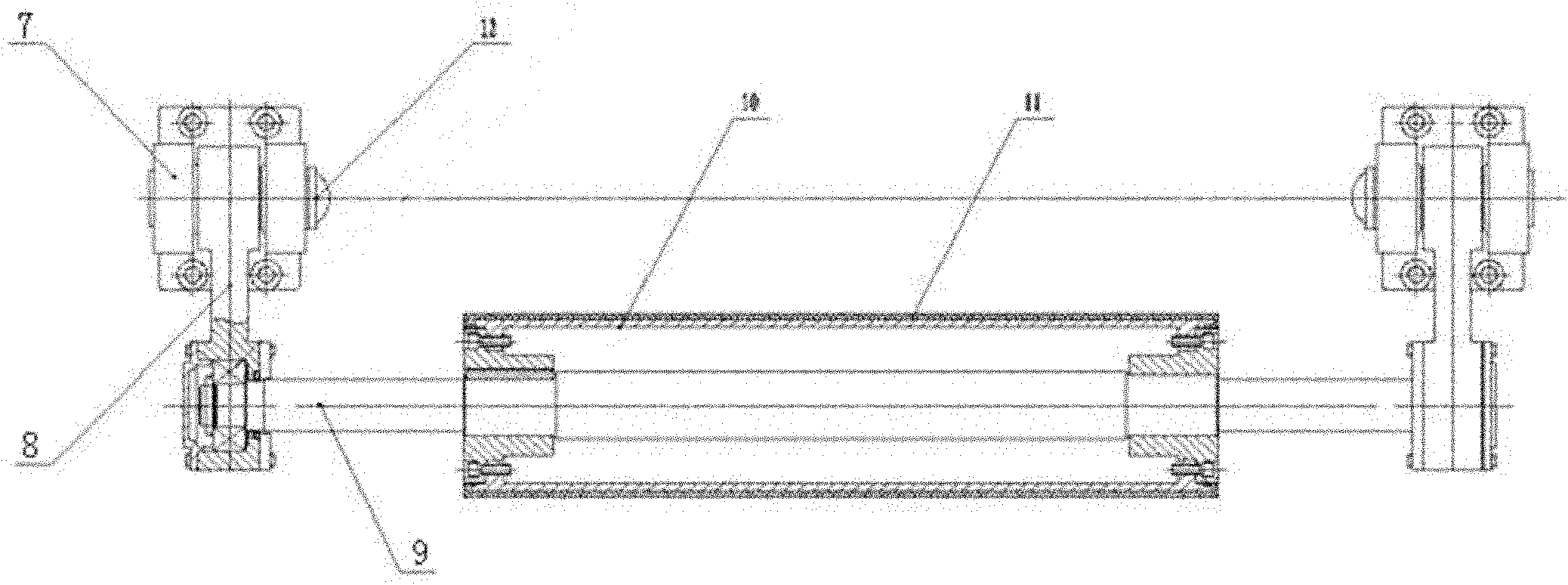
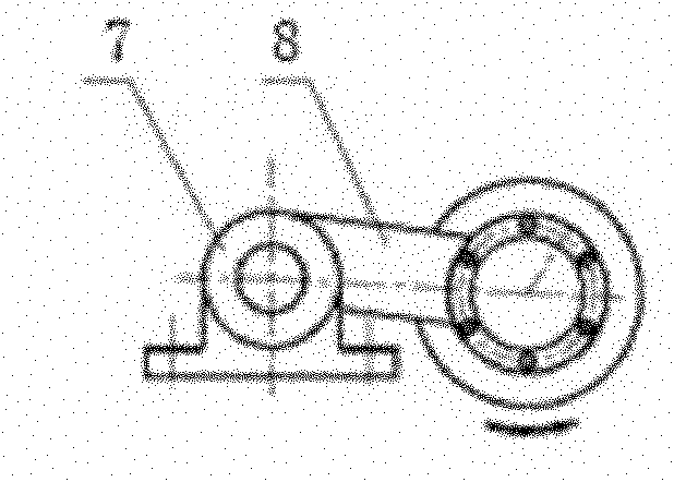
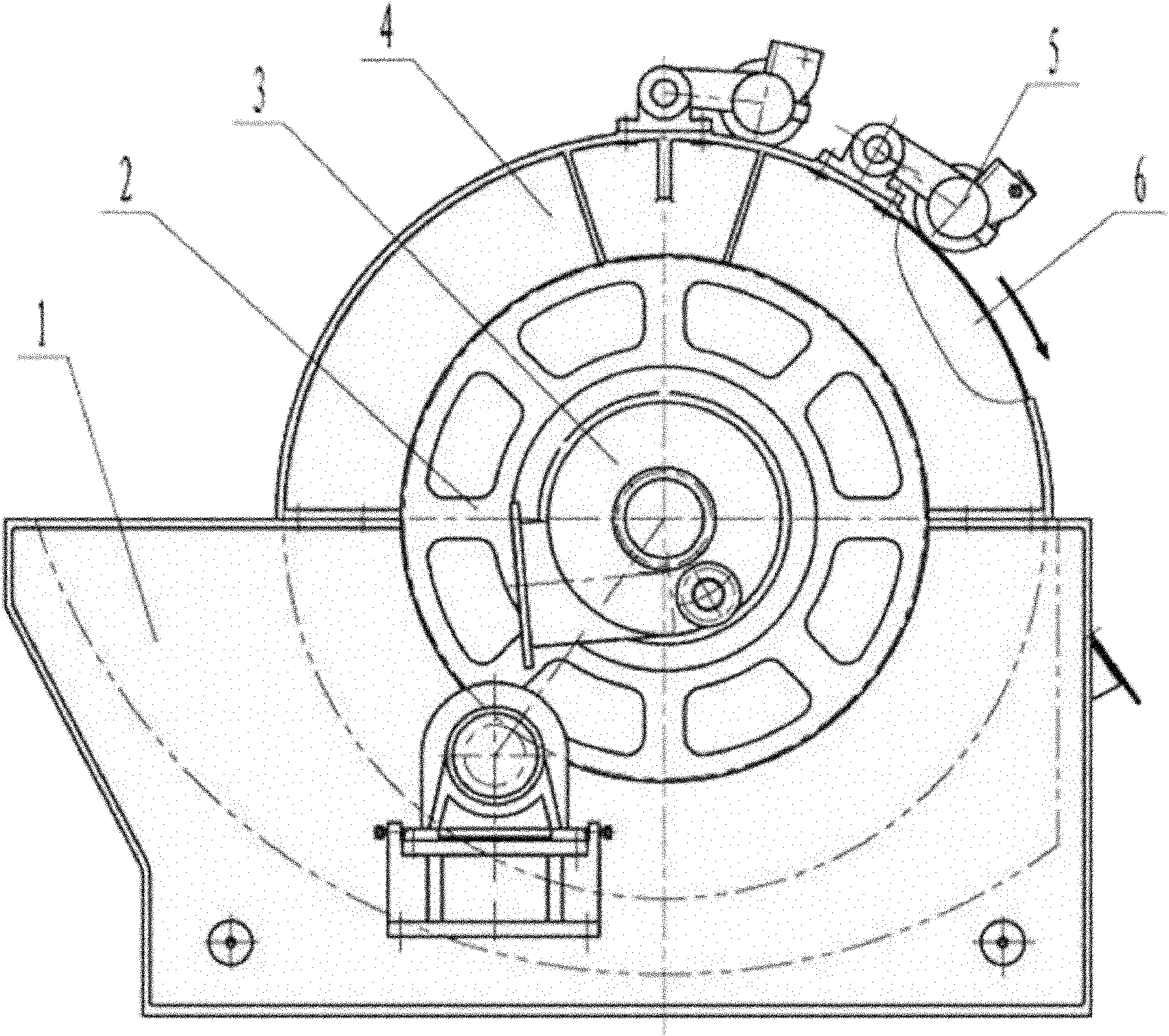
[0016] Such as figure 1 , figure 2 and image 3 As shown, the drum 6 is supported on the frame 4 by the journals at its two ends, and is immersed in the slurry tank 1 with a certain liquid level. The driving device 2 drives the drum 6 to rotate, and the distribution head 3 communicating with the drum 6 Connect the vacuum system, the drum 6 absorbs the filter slurry in the filter slurry tank 1, and forms a filter cake layer with a certain thickness on the outer peripheral surface of the drum 6 . The pressure roller device 5 is installed above the drum 6, and its centerline is parallel to the centerline of the drum 6; the two ends of the pressure roller body 10 in the pressure roller device 5 are connected with a pressure roller shaft 9, and the pressure roller shaft 9 is supported by a bearing 13 The two support arms 8 can rotate freely, the other end of the suppo...


PUM


Abstract

The invention discloses a press roller device for a vacuum rotary drum filter. In the press roller device (6), two ends of a press roller body (10) are connected with a press roller shaft (9); the press roller shaft (9) is supported on a support arm (8) through a bearing (13), and the other end of the support arm (8) is connected to a bearing pedestal (7) through a pin roll (12); the bearing pedestal (7) is fixed on a frame (4); and a modified nylon material layer (11) is coated on the outer surface of the press roller body (10). The modified nylon material layer (11) in the device has extremely high corrosion resistance and abrasion resistance, can effectively prolong the service life of the press roller device (6); and the rotation of the roller body (10) is smoother and the surface of a rolled filter cake is flatter, so that a scraper cleaning device is not required any more, the filter structure is simplified, the manufacturing cost and operation maintenance cost are reduced, and the defects generated by the scraper cleaning device are effectively overcome.

Description

technical field [0001] The invention relates to an accessory device of a filter, in particular to a pressure roller device of a vacuum drum filter. Background technique [0002] Drum vacuum filter with external filter surface is widely used in chemical industry, metallurgy, food, petroleum refining, paper making and wastewater treatment and other industries. Its working principle is: the rotating drum on which the filter medium is laid is submerged in a slurry tank with a certain liquid level, and the drum space is divided into several compartments by radial ribs, and each compartment is connected to the journal through a separate channel. On the distributing head, the corresponding pipeline of the fixed valve seat passes through the static and dynamic dislocation air discs of the distributing head to draw vacuum, input compressed air and other media to each compartment of the drum in a certain order, so as to ensure that each compartment completes the filtration in sequence...

Claims


Application Information

Patent Timeline
Patent Type & Authority Applications(China)
IPC IPC(8): B01D33/64B01D33/06
Inventor 邓亲华邓翔张海张云杰
Owner CHENGDU TIANBAO HEAVY IND
Learn More