Integrated low-carbon micro-discharge energy-saving and emission-reduction boiler system

A technology of energy saving and emission reduction, boiler body, applied in the direction of indirect carbon dioxide emission reduction, non-flammable liquid/gas transportation, combustion method, etc., can solve the problems of wasting land resources, affecting the appearance of the city, environmental heat pollution, etc., and achieve full utilization , Good emission reduction effect, heat pollution reduction effect

Active Publication Date: 2011-03-16
慧生能源科技有限公司
View PDF8 Cites 10 Cited by
  • Summary
  • Abstract
  • Description
  • Claims
  • Application Information

AI Technical Summary

Problems solved by technology

Because it burns coal and other fuels, the pollution of carbon dioxide and sulfur dioxide caused by its emissions has become a problem in the field of environmental protection. The current large boilers need to be discharged at high altitudes through chimneys to reduce pollution to living spaces. Chimneys not only affect the overall health of the city It is beautiful and wastes precious land resources; in addition, the high-temperature flue gas directly discharged after boiler combustion not only wastes a lot of heat energy, causes energy waste, but also brings thermal pollution to the environment, so the issue of boiler energy saving is also very important; at present , there is no integrated system for secondary combustion of flue gas discharged after boiler combustion

Method used


Image

  • Integrated low-carbon micro-discharge energy-saving and emission-reduction boiler system
  • Integrated low-carbon micro-discharge energy-saving and emission-reduction boiler system
  • Integrated low-carbon micro-discharge energy-saving and emission-reduction boiler system

Examples


Embodiment Construction

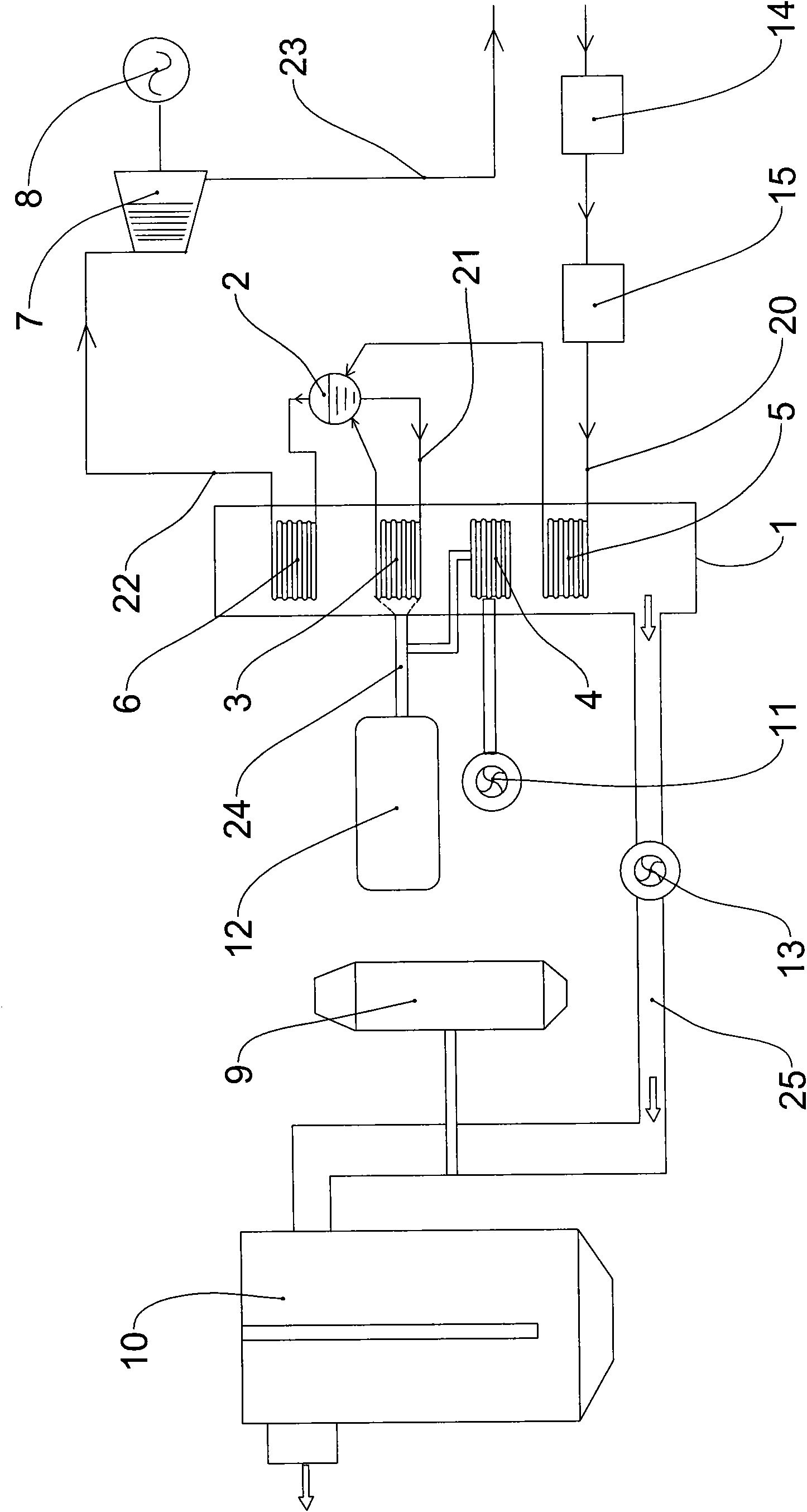
[0019] Such as figure 1 As shown, this embodiment includes boiler body 1, steam drum 2, heat exchanger 3, preheater 4, economizer 5, superheater 6, steam turbine 7, generator 8, flue gas secondary combustion device 9, desulfurization The dust removal device 10, the blower 11, the oxygen-enriched air supply device 12, the flue gas induced draft fan 13, the steam drum 2 and the heat exchanger 3 form a hot water heating circulation loop through the circulating heating pipeline 21, and the economizer 5. It is connected to the water inlet of the steam drum 2 through the boiler feed water pipeline 20. The economizer 5 absorbs relatively low-temperature flue gas, which reduces the exhaust gas temperature of the flue gas, reduces the loss of exhaust gas, and saves fuel , the efficiency is improved, the temperature of the feed water is increased, and the wall temperature difference will be reduced when entering the steam drum 2, the thermal stress will be reduced accordingly, and the s...


PUM


Abstract

The invention discloses an integrated low-carbon micro-discharge energy-saving and emission-reduction boiler system. The system comprises a boiler body (1), a steam drum (2), a heat exchanger (3), a preheater (4), an economizer (5), a superheater (6), a steam turbine (7), a generator (8), a secondary smoke combustion device (9), a desulfuration and dust collect unit (10), an air blower (11) and a smoke exhauster (13), wherein the steam drum (2) and the heat exchanger (3) constitute a hot-water heating circulation loop, the economizer (5) is connected with the steam drum (2), and the air blower (11) feeds air to the preheater (4); the steam drum (2) is connected with the superheater (6), and then connected with the steam turbine (7) by a superheated steam pipe (22); the steam turbine (7) is connected with a low-pressure steam pipe (23), and the generator (8) is linked with the steam turbine (7); and the outlet of a gas duct of the boiler body (1) is connected with a smoke pipe (25), and the smoke exhauster (13) is arranged on the smoke pipe (25), and sequentially feeds smoke into the secondary smoke combustion device (9) and the desulfuration and dust collect unit (10) so as to process and discharge the smoke.

Description

technical field [0001] The invention relates to an integrated system of low-carbon micro-emission energy-saving and emission-reduction boilers. Background technique [0002] As an important thermal energy equipment, boilers are widely used in many industrial and civil fields. Because it burns coal and other fuels, the pollution of carbon dioxide and sulfur dioxide caused by its emissions has become a problem in the field of environmental protection. The current large boilers need to be discharged at high altitudes through chimneys to reduce pollution to living spaces. Chimneys not only affect the overall health of the city It is beautiful and wastes precious land resources; in addition, the high-temperature flue gas after boiler combustion is directly discharged, which not only wastes a lot of heat energy, causes energy waste, but also brings thermal pollution to the environment, so the issue of boiler energy saving is also very important; at present However, there is no in...

Claims


Application Information

Patent Timeline
Patent Type & Authority Applications(China)
IPC IPC(8): F22B33/18F23L7/00F23J15/04F01D15/10F01K11/02
CPCY02E20/34
Inventor 聂民邹宗伍
Owner 慧生能源科技有限公司
Why Eureka
Try Eureka