Self-circulation fuel cell control system and method thereof

A fuel cell system and fuel cell technology, applied in the direction of fuel cells, fuel cell grouping, fuel cell additives, etc., can solve problems such as difficult continuous work, difficult control, high working pressure of fuel cells, etc., to achieve high oxidant concentration, high operating The effect of convenience and simple structure

Active Publication Date: 2011-03-23
QINGDAO HANHE HYDROGEN ENERGY EQUIP TECH CO LTD
View PDF6 Cites 8 Cited by
  • Summary
  • Abstract
  • Description
  • Claims
  • Application Information

AI Technical Summary

Problems solved by technology

[0009] 1. Limited by the oxygen concentration in the air, the fuel cell requires a higher working pressure, and the booster circulation pump has a larger workload;
[0010] 2. The water generated by the reaction is mainly discharged together with the air, which is difficult to control and cannot be effectively used in the fuel cell. An additional humidifier is required for the incoming air or better moisturizing measures need to be added to the fuel cell;
[0011] 3. The water generated by the reaction needs a large pressure to be discharged, which further causes the work burden of the booster circulation pump;
[0012] 4. The heat generated by the reaction is discharged together with the air, and cannot be well utilized in the fuel cell. Even if it is partially used in the fuel cell by means of heat exchange, the heat generated by the reaction is not easy to control due to its open structure
[0013] 5. Although the filter can filter out some impurities in the air, it is difficult to work continuously in a highly polluted environment, which seriously affects the performance of the fuel cell
[0014] 6. Although the booster circulation pump can be used to boost the pressure, the workload of the booster circulation pump is further increased in the environment where the oxidant is thin, such as on the plateau, which makes it difficult to ensure the electrochemical reaction speed of the fuel cell, and also affects the performance of the fuel cell. will have a major impact
The disadvantage of this scheme is that if the recovery pump fails, the fuel cell stack cannot function properly

Method used


Image

  • Self-circulation fuel cell control system and method thereof
  • Self-circulation fuel cell control system and method thereof
  • Self-circulation fuel cell control system and method thereof

Examples


Embodiment 1

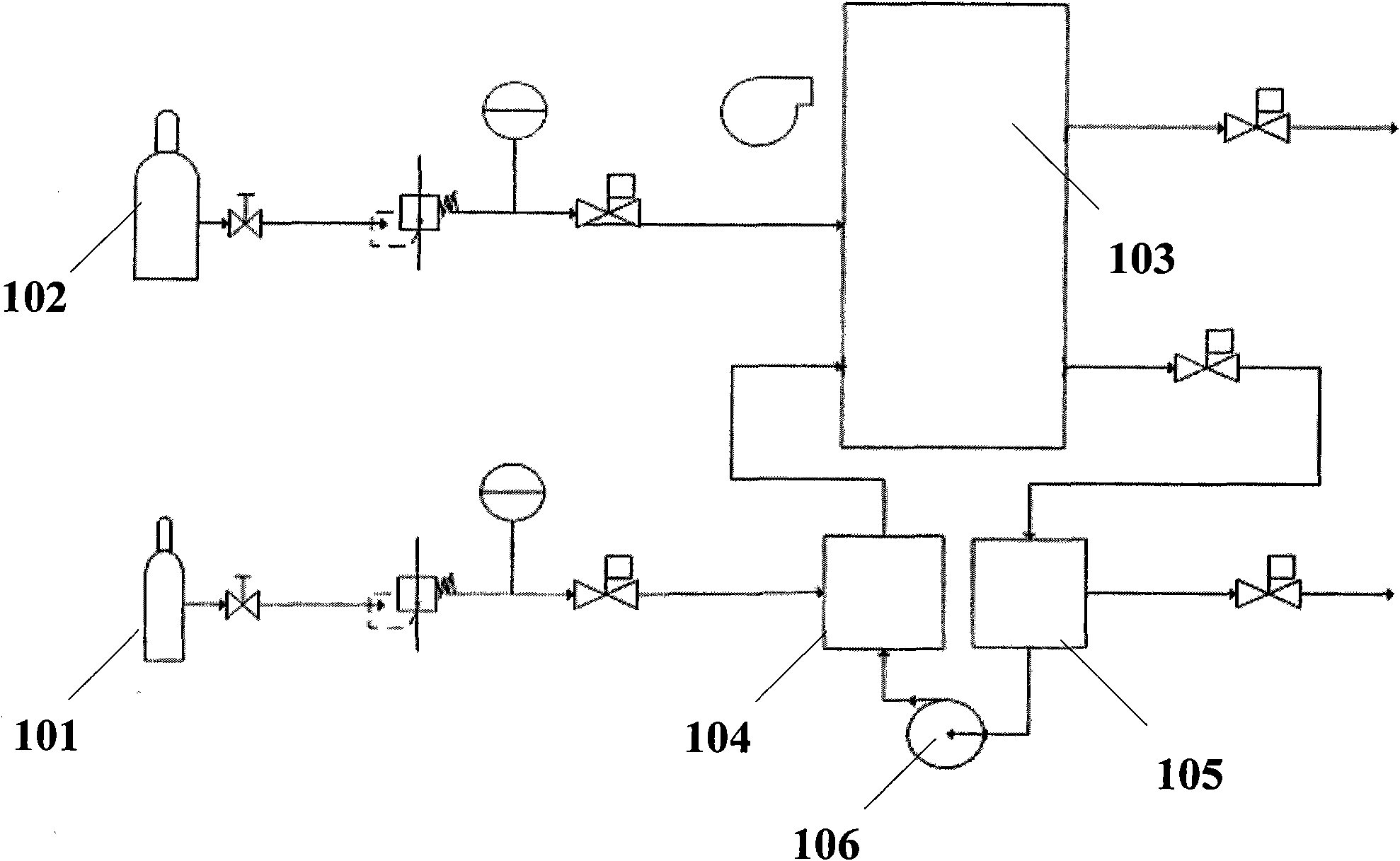
[0067] Such as figure 1 As shown, a ring fuel cell system includes a fuel cell stack 103 with a fuel channel and an oxidant channel, the fuel channel is provided with an oxidant container 101 for containing oxidant, and the oxidant container 101 is connected to the inlet of the fuel cell stack 103 A first mixer 104 is connected to the oxidant passage at the outlet end of the fuel cell stack 103, and a gas-water separator 105 and a first booster circulation pump 106 are arranged in sequence on the outlet end of the fuel cell stack 103, and the first booster circulation pump 106 The output end of is connected with the first mixer 104 pipeline. The outlet end of the fuel cell stack 103 drains intermittently to the gas-water separator 105 , the water is removed, and the gas is sucked into the first mixer 104 through the first pressurized circulating pump 106 , mixed with the oxidant, and then enters the fuel cell stack 103 . This solution is relatively reliable, but still require...

Embodiment 2

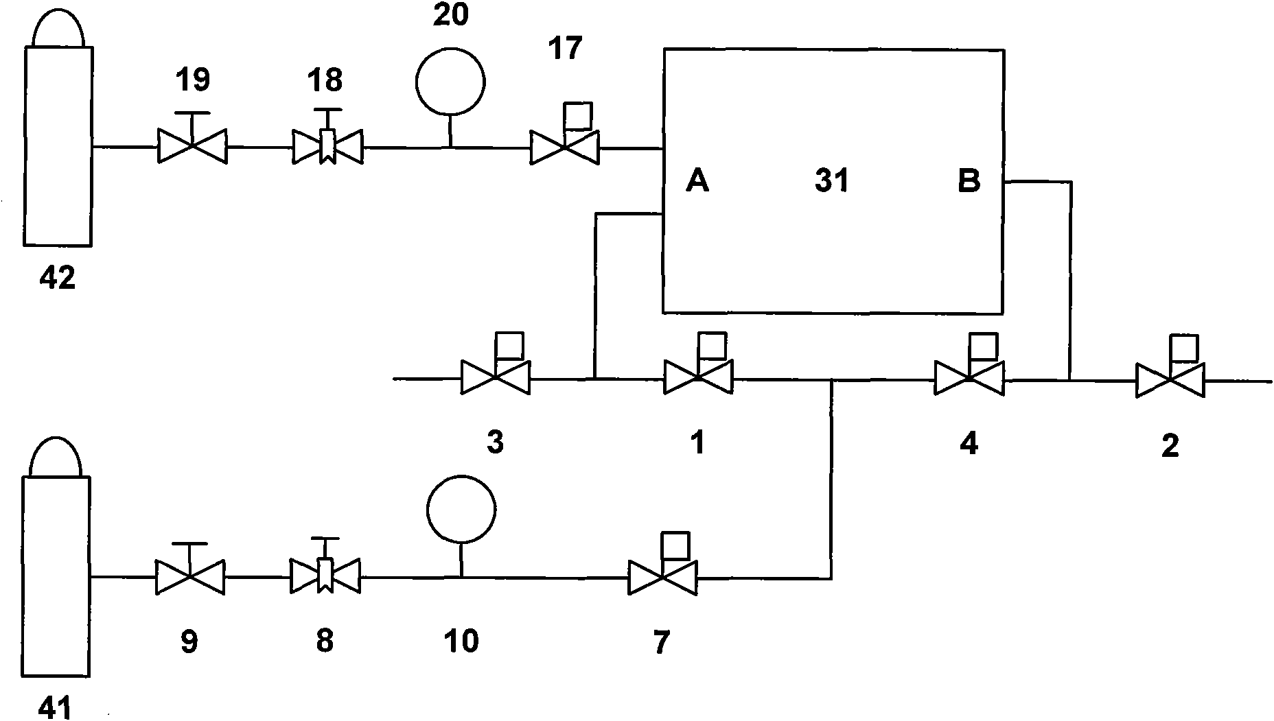
[0078] Such as image 3 As shown, a self-circulating fuel cell system of the present invention includes a fuel cell stack 31 provided with fuel channels and oxidant channels. The fuel cell stack 31 enters and exhausts bidirectionally. One end of the oxidant channel is provided with an oxidant container 41 for containing oxidant. Both ends of the fuel cell stack 31, a bypass pipe with a third solenoid valve 3 is connected between the first solenoid valve 1 and the fuel cell stack 31, and the fourth solenoid valve 4 is connected to the fuel cell stack 31. A bypass pipe with a second solenoid valve 2 is connected between the battery stacks 31 . The oxidant channel is sequentially connected with a stop valve 9 , a pressure regulating valve 8 , a pressure sensor 10 , and an inlet solenoid valve 7 . One end of the fuel channel is provided with a hydrogen container 42 for holding hydrogen, and the other end is divided into two paths, which are respectively connected to the two ends...

Embodiment 3

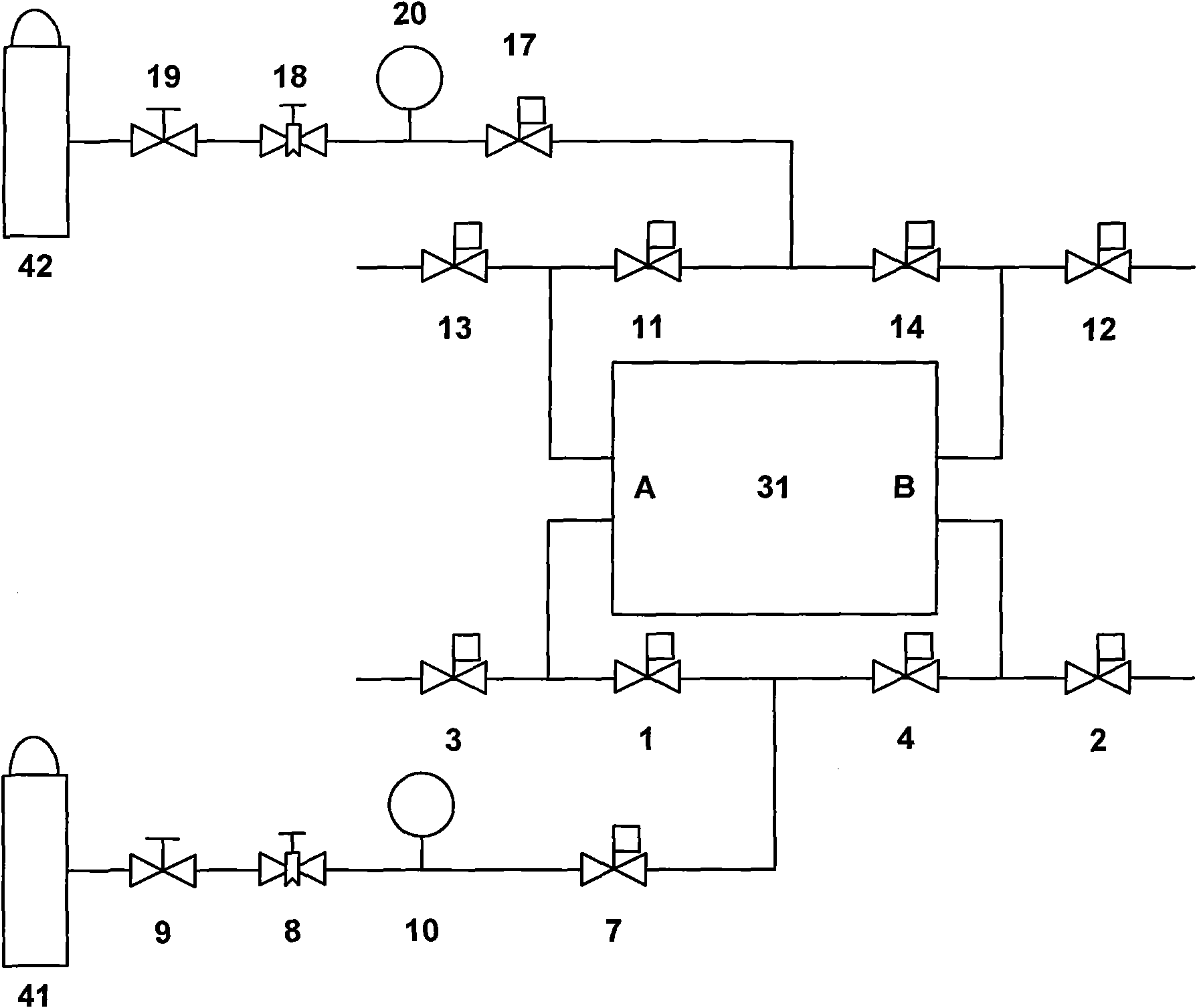
[0081] Such as Figure 4 As shown, a self-circulating fuel cell system of the present invention includes a fuel cell stack 31 provided with a fuel channel and an oxidant channel. The other end of the oxidant container 41 containing the oxidant is divided into two circuits, which are respectively connected to the two ends of the fuel cell stack 31 through the first electromagnetic valve 1 and the fourth electromagnetic valve 4. The first electromagnetic valve 1 and the fuel cell A first gas-water separator 5 is arranged between the electric stacks 31, and a bypass pipe with a third solenoid valve 3 is connected to the first gas-water separator 5, and the fourth solenoid valve 4 is connected to the fuel cell electric A second gas-water separator 6 is provided between the stacks 31 , and a bypass pipe with a second solenoid valve 2 is connected to the second gas-water separator 6 . The oxidant channel is sequentially connected with a stop valve 9 , a pressure regulating valve 8 ...


PUM


Abstract

The invention discloses a self-circulation fuel cell control system and a method thereof. A fuel cell electric pile charges and exhausts gas in a bidirectional way, one end of an oxidant passage is provided with a container used for holding an oxidant, the other end of the oxidant passage is divided into two paths which are respectively connected with two ends of the fuel cell electric pile through a first solenoid valve and a fourth solenoid valve, a bypass pipe provided with a third solenoid valve is connected between the first solenoid valve and the fuel cell electric pile, and a bypass pipe provided with a second solenoid valve is connected between the fourth solenoid valve and the fuel cell electric pile. By sequentially opening and closing the solenoid valves for the control of bidirectional gas charge and exhaust, the oxidant is not needed to be filtered, humidified or heated; and the invention has the advantages of low working pressure, good sealability, simple structure, convenient operation and low cost.

Description

technical field [0001] The invention belongs to the field of fuel cell systems, and in particular relates to a self-circulating fuel cell control system and a method thereof. Background technique [0002] A fuel cell stack is generally composed of a plurality of battery cells, each of which includes two electrodes (bipolar plates) and a mold electrode assembly (MEA) separating the two electrodes, and is assembled in series with each other to form a fuel cell stack. The electrochemical reaction is achieved by supplying the appropriate reactants to each electrode, ie fuel to one electrode and oxidant to the other, creating a potential difference between the electrodes and thereby generating electrical energy. [0003] In a typical fuel cell system using oxygen in the air as the oxidant, fuel and air enter the fuel cell through a set of channels respectively. Before the air enters the fuel cell, it needs to be treated as follows: [0004] 1. Filter the air through a filter to...

Claims


Application Information

Patent Timeline
Patent Type & Authority Applications(China)
IPC IPC(8): H01M8/24H01M8/04H01M8/04089
CPCY02E60/50
Inventor 高勇
Owner QINGDAO HANHE HYDROGEN ENERGY EQUIP TECH CO LTD
Why Eureka
Try Eureka